
Structural Composite
Structural Composite论文代写 As part of this process, the filament is laid down in a way that allows maximum strength to be provided when required.
Contents Structural Composite论文代写
structural composite………………………………………………………………………………………….1
Chapter Two: Literature Review………………………………………………………………………….1
1.1 Composites…………………………………………………………………………………………………..1
1.1.1 History of Composites…………………………………………………………………………………1
1.1.2 Type of Composites……………………………………………………………………………………2
1.1.3 Composite Classifications…………………………………………………………………………..4
1.1.4 Applications of composites…………………………………………………………………………6
1.2 Reinforcement Fibres……………………………………………………………………………………7
1.2.1 Glass Fibre………………………………………………………………………………………………..7
1.2.1.1 Advantages and Disadvantages of Glass Fibre……………………………………………8
1.2.2 Carbon Fibre…………………………………………………………………………………………….9
1.2.2.1 Advantages and Disadvantages of Carbon Fibre:………………………………………..9
1.2.3 Aramid……………………………………………………………………………………………………10
1.3 Natural Fibre……………………………………………………………………………………………..10
1.3.1 History of Natural Fibres…………………………………………………………………………..11
1.3.2 Applications of Natural Fibres…………………………………………………………………..12
1.3.3 Advantages and Disadvantages of Natural Fibres………………………………………..12
1.3.4 Natural Fibre as Reinforcement for Composites………………………………………….14
1.3.5 Mechanical Properties of Natural Fibre Composites…………………………………….15
1.4 Matrix……………………………………………………………………………………………………….20
1.4.1 Types of Fibre (Resins Polymers)………………………………………………………………20
1.5 Manufacturing Process of Composites………………………………………………………….24
1.5.1 Hand Lay-up……………………………………………………………………………………………24
1.5.2 RTM……………………………………………………………………………………………………….25
1.5.3 Compression Moulding…………………………………………………………………………….26
1.6 Summary of literature review………………………………………………………………………27
2 References:………………………………………………………………………………………………….28
3 Appendices…………………………………………………………………………………………………..33
3.1 Appendix A………………………………………………………………………………………………..33
3.2 Appendix B……………………………………………………………………………………………….33
3.3 Appendix C……………………………………………………………………………………………….33
3.4 Appendix D……………………………………………………………………………………………….33
3.5 Appendix E.1……………………………………………………………………………………………..34
3.6 Appendix E.2…………………………………………………………………………………………….35
3.7 Appendix F.2……………………………………………………………………………………………..36
3.8 Appendix F.3…………………………………………………………………………………………….37
3.9 Appendix F.4…………………………………………………………………………………………….38
3.10 Appendix G.1…………………………………………………………………………………………..39
3.11 Appendix G.2……………………………………………………………………………………………40
3.12 Appendix H.1……………………………………………………………………………………………41
3.13 Appendix H.2…………………………………………………………………………………………..42
3.14 Appendix H.3…………………………………………………………………………………………..43
3.15 Appendix H.4…………………………………………………………………………………………..44
3.16 Appendix H.5…………………………………………………………………………………………..45
3.17 Appendix H.6…………………………………………………………………………………………..46
3.18 Appendix I……………………………………………………………………………………………….47
3.19 Appendix J.1…………………………………………………………………………………………….47
3.20 AppendixJ.2……………………………………………………………………………………………48
3.21 Appendix J.3……………………………………………………………………………………………49
Chapter Two: Literature Review Structural Composite论文代写
1.1 Composites
A structural composite can be described as a material structure comprising at least two different phases on a microscopic scale, the mechanical properties and performance of which are intended to be greater than those basic materials working independently. One such phase, referred to as reinforcement, is commonly discontinuous, stronger and stiffer, whilst the weaker phase is known as matrix, which is less stiff. Commonly, owing to the chemical interphase app
arent between the processing effects, there is the presence of the interphase between the matrix and reinforcement.
Importantly, the properties of the continuous, distribution and geometry of the phases dictate the properties of the composite materials, with the volume fraction of reinforcement or fibre volume ratio recognised as being one of the most important parameters. Notably, the application and type of composite material governs the role played by the composite system. Structural Composite论文代写
For instance, some stiffening and localised material strengthening is commonly delivered by the reinforcement, such as through short fibres or particles, in the case of low-to-medium performance composite material; in contrast, however, the matrix is understood to be the main load-bearing constitutes leading the material’s mechanical properties. Markedly, in regard to high-performance structural composites, the stiffness and strength in terms of the fibres are determined by the usually continuous fibre-reinforcement, which acts as the material’s backbone [9]. Figure 1 shows the structure of composite material. Mechanical Behaviours of Composite Materials and its Characteristics are presented in Appendix E.1 and E.2
1.1.1 History of Composites
In their research, it was stated by Strong [10] and Johnson [11] that, throughout history, composite materials has been recognised as adopting a number of different forms. For instance, at approximately 1500 BC, the first use of composites is known to have occurred when Egyptians combined mud and straw to create durable and strong infrastructure. In addition, there are a number of other natural composites, including coconut palm leaf and wood, for example. Notably, the history of modern composites began with the development of plastics, by scientists, during the 1930s.
It is relevant to highlight that, during World War II, both engineers and researchers were seeking to establish lighter materials with low costs to replace heavy, expensive materials commonly used for military purposes. Accordingly, various technological solutions were developed. Subsequently, during the 1970s onwards, fibre-reinforced polymer matrix composites have been widely used in a number of different industries, including aerospace, automotive, construction, leisure, and sports, as a result of their low cost, strength and weight, as has been recognised by Haibin [12] and Wambua [3]. Structural Composite论文代写
1.1.2 Type of Composites
The most common types of composite material are:
- Fibrous composite materials, comprising fibres in a matrix. As shown in Figure 2 (a).
- Laminated composite materials, comprising layers of certain materials. As shown in Figure 2 (B).
- Particulate composite materials, comprising particles in a matrix. As shown in Figure 2 (C).
- Combinations of some or all of the above.
1.1.2.1 Fibrous Composite Materials:
It is known that, in various forms, long fibres are characteristically a great deal stronger and stiffer than the same material in a bulk form. For instance, whilst glass fibres are known to have strengths of 400,000–70,000 psi (2800–4800 MPa) in laboratory-prepaid forms, ordinary plate glass, on the other hand, fracture at a stress of only a few thousand pounds per square inch (lb/in^2 or psi) (20 MPa).
With this in mind, it is then clear that the physical composition and geometry of a fibre are both fundamental in terms of the overall assessment of its strength, and therefore must be taken into account in regard to structural applications. More specifically, it should be noted that it is owing to the generally flawless structure of a fibre that there is inconsistency of fibres in terms of different properties when compared with the bulk form. In addition, in the case of fibres, there are a lesser number of internal imperfections than in bulk materials: for instance, when considering materials with disarticulations, there are fewer dislocations in case of fibre form than bulk form [9]. Structural Composite论文代写
1.1.2.2 Laminated Composite Materials:
Laminated composite materials are known to have two or more different materials, affixed together, forming different layers. Notably, the lamination process is implemented in order to join the most positive and valuable features of bonding materials and constituent layers so as to achieve a more valuable end material. Lamination is able to highlight and accentuate a number of different properties, including aesthetics, corrosion, acoustical insulation, low weight, resistance, stiffness, strength, thermal insulation and wear, with such assertions supported in the following paragraphs [13, 12].
1.1.2.3 Particulate Composite Materials:
Particulate composite materials comprise the metallic or non-metallic particles of various different materials positioned within the metallic or non-metallic matrix of another material. Accordingly, there are four different combinations of the aforementioned structures, namely:
- Non-metallic particles in non-metallic matrix composite materials.
- Metallic particles in non-metallic matrix composite materials.
- Non-metallic particles in metallic matrix composite materials.
- Metallic particles in metallic matrix composite materials [9].
1.1.2.4 Advantages and Disadvantages of Composite Materials
Composite materials, in the main, are considered to be either lightweight or corrosion-resistant. In addition to such benefits, such materials are also very accommodating in terms of manufacture, and can be formed in either simple or complicated shapes. Furthermore, the life-part performance is acknowledged as being longer in the case of composite materials than metal parts [14, 15]. Notably, there are a number of additional advantages, including:
Electrical properties: GRP is a valuable electrical insulator, which is useful for a number of different structures. Structural Composite论文代写
Fatigue: Certain composites are fatigue- and corrosion-resistant, especially those with carbon-reinforcement.
Finish: Finish can be easily incorporated during manufacture.
Thermal properties: Components can be designed with very low, even zero, thermal properties.
Wear-resistant: carbon fibre materials behave well owing to the establishment of a graphitic layer.
However, although there are numerous advantages, there are also various disadvantages, including a lack of inspectability and ductility; thus, it can be stated that one application’s advantages may be a disadvantage for another application[14, 15 and 16]. Some drawbacks include:
- Effect of water absorption on their properties.
- High coefficient of thermal expansion.
- Low impact resistance.
- Low maximum working temperature.
- Sensitivity to radiation.
1.1.3 Composite Classifications Structural Composite论文代写
1.1.3.1 Polymer Matrix Composites (PMCs):
Polymer matrix composite materials have undergone the most significant development across the globe, and can now be formed into a number of different shapes made from boron or carbon fibres, attached with the use of organic polymer matrix. Notably, the properties of such an amalgamation can help to ensure corrosion and weathering are avoided, and further deliver a notable degree of strength and modulus, thus facilitating utilisation in aerospace- and commercial-related applications.
It is widely recognised that polymer matrix composites are very easily formed, particularly when compared with other fibre composites, regardless of whether the polymer is thermoplastic or thermoset; this is owing to the fact that the procedure of fabrication necessitates low temperatures. Accordingly, the fabrication of PMCs may be complicated and may adopt large shapes, and have been widely used in a number of commercial and aerospace functions. Markedly, such reinforced plastics are viewed as being a cooperative and interactive combination of high-performance matrices and fibres. Figure 3 shows a picture of fatigue in matrix composite.
1.1.3.2 Metal Matrix Composites:
Such composites comprise metal alloys reinforced with the use of continuous fibres, which are known to be resistant to high temperatures but which remain heavy; thus, it can be seen that the use of PMCs is most preferable owing to their attributes of being moisture-resistant, amongst others, therefore facilitating involvement in a number of applications. Structural Composite论文代写
1.1.3.3 Ceramic Matrix Composites:
In the context of different applications, advanced, high-performance structures can be produced through making use of the opportunities delivered by new processing routes and materials. Markedly, one such promising material is that of CMCs, i.e. ceramic matrix composites. Through joining together various ceramic matrix materials alongside appropriate fibres, there can be the creation and customisation of new properties for use in technical fields. One of the most important of advantages offered by CMCs is their natural resistance to high temperatures. Figure 4 shows SEM view on ceramic matrix.
1.1.3.4 Carbon-carbon Composites:
Carbon-carbon composites comprise reinforced carbon fibre set in a high temperature-resistant carbon matrix, which can be utilised in both structural and non-structural composites.
1.1.3.5 Intermetallic Composites:
This particular type of composite is most commonly utilised in the case of gas turbine engines for both civil and military applications, and is known to benefit from extremely low density. Structural Composite论文代写
1.1.4 Applications of composites
It is known that composite materials can be applied and produced in a number of different ways, with such developments spanning back many years. During modern times, composites are recognised as being appropriate for those applications requiring finite tolerance, precision engineering, the simplification of parts, and weight savings [16].Importantly, advanced composites were first applied in military contexts, both in the wings and fuselage, in addition to engines’ outer casings. Accordingly, those countries known to have developed industrial military complexes are understood to make use of such applications, i.e. the UK, US, France, Germany and Italy, in various different arenas, including:
Aircraft: aircraft industries were the first to utilise fibre-reinforced composites, which are fatigue-resistant owing to their properties concerned with aluminium usages. Moreover, FRP composites are used by commercial and military aircrafts owing to total weight reduction; therefore, there are fuel savings to be made as a result of speed increases.
Automotive application:
a number of different vehicles, namely buses, cars and trains, all use FRP composites owing to their low costs, and are therefore viewed as being suitable for high-volume production. Structural Composite论文代写
Boats: the majority of boat applications are concerned with yachts and catamarans, comprising epoxy resin or carbon fibre-reinforced vinyl in both the masts and hulls.
Space:
metal matrix composites facilitate composite materials properties to provide benefits by conducting heat away from sensitive parts; this is not achievable by insulating resins. Moreover, they can also be implemented in the case of smaller structure, including optical platforms and solar arrays [17].
Additional applications: FRP composites are now recognised as having uses in everyday life, such as in the case of bulletproof vests, cars, computer housing, golf clubs, high-performance bikes, prosthetics, and a wide range of other additional products.
In addition, there are various aspects of composite materials utilisation, including automotive applications, civil engineering, ground transport, infrastructure, marine, and on the seabed [14, 17 and 18]. Figure 5 shows composite applications.

1.2 Reinforcement Fibres Structural Composite论文代写
Owing to the fact that composite structure comprises at least two phases on a microscopic scale, it is common for one phase to be stronger and stiffer than the other(s); this is referred to as composite reinforcement, whilst the weaker is the matrix [9, 20]. Importantly, composite materials can be reinforced through the use of fibre, of which there are many different types utilised for this purpose. The most common of these are discussed in the following paragraphs.
1.2.1 Glass Fibre
Glass fibre is a valuable composite material created when a plastic material is reinforced with the use of glass fibre in the form of strand mat. The plastic material, which is commonly polyester resin, is utilised with the aim of providing the right colour, finish and shape, whilst mechanical strength is achieved through the glass fibres, which are positioned in various different directions. The degree to which reinforcement can be implemented rests upon the positioning of the reinforcement: for instance, the reinforcement area may be as great as 0.9 if long strands are placed parallel to one another. Structural Composite论文代写
It should be noted that the reinforcement area fraction can be calculated by taking the cross-sectional area of reinforcement and dividing this by the total cross-sectional area. Importantly, the reinforcement area fraction may be as great as 0.75 with woven strand fabrics, although this figure is markedly lower, i.e. 0.5, in the case of chopped strand mat; however, this remains adequate. Clearly, the composite is weaker if the reinforcement area fraction is lower. Figure 6 shows glass fiber. It is known that, in the context of fibre manufacture, the glasses used do not possess the same configurations as those considered above. Rather, the glass grades implemented with the aim of achieving fibre-reinforcement are as follows: Structural Composite论文代写
-C-glass, otherwise known as chemical glass, is utilised in regard to chemical plant equipment, and is low in aluminium oxide and calcium oxide.
This particular grade offers good resistance in regard to acid attack, and is also used for fibreglass surfacing mats, which need to resist environmental attacks and ensure the substrate, and its reinforcement, are protected.
-E-glass, otherwise referred to as electrical grade, is known to possess valuable insulation properties, and is therefore used for manufacturing glass-reinforced printed circuit boards. This grade is water- and alkalis-resistant, and delivers high levels of strength.
-M-glass, otherwise known as high-modulus grade, is expensive and thus utilised only in cases of high-strength applications where the high costs are counterbalanced by the utilisation and sound direction of its valuable properties. Structural Composite论文代写
-S-glass, otherwise referred to as high-strength grade, fibre is manufactured in continuous filaments and woven into fabrics and mats for boat hulls and pressure vessels [21].
1.2.1.1 Advantages and Disadvantages of Glass Fibre
Advantages:
-Corrosion-resistant
-High strength
-Low cost
-Non-conductive
-Non-flammable.
Disadvantages:
-Workable strength is reduced during instances of moisture absorption
-In crescent of strength as the surface flaws grow under cyclic load in fatigue application [14, 17, 18 and 22].
1.2.2 Carbon Fibre
Carbon fibre, which is plastic reinforced with the use of a graphite textile, is known to possess a number of valuable properties, including high fatigue strength, high tensile strength, and low coefficient of linear thermal expansion, to name a few. However, there are also a number of drawbacks, including high electrical conductivity and low impact resistance. Notably, there are two different types of carbon fibre, namely pitch precursors and textile precursors [13]. Undoubtedly, carbon is acknowledged as being a high-performance fibre material, which is the most widely utilised resin reinforcement in the context of advanced polymer composites. This is owing to various reasons, including:
-
Carbon fibres are known to offer the greatest specific modulus and strength when compared alongside all reinforcing fibre materials.
- Carbon fibres maintain their high tensile modulus and strength, regardless of raised temperatures, although it is recognised that high-temperature oxidation may nevertheless pose an issue. Structural Composite论文代写
When at room temperature, carbon fibres are acknowledged as being unaffected by moisture and a number of different acids, bases and solvents.
There is extensive use of carbon reinforcement polymer composites in the case of recreational and sports equipment, as well as in filament-wound rocket motor cases [21]. Figure 7 shows carbon fiber.
1.2.2.1 Advantages and Disadvantages of Carbon Fibre:
Advantages: Disadvantages:
-High fatigue strength. – High electrical conductivity.
-High tensile strength. -Low impact resistance.
-High thermal conductivity. -Low strain-to failure [14, 22].
-Low compressive strength
-Low cost.
-Low Specific gravity.
-Relatively low modulus [17,18].
1.2.3 Aramid Structural Composite论文代写
This type of fibre is man-made comprising a significant degree of crystallinity, implemented within the composites arena. Through the use of aromatic rings connected through hydrogen bridges, the molecular chains are supported and firm. This amalgamation justifies the significant strength [23].
Importantly, aramid fibres offer two different levels of stiffness, one of which delivers an elasticity modulus of approximately 60GPa, whilst the other is recognised as being 130GPa. In terms of utilisation, the fibres are commonly implemented in those composites with polymer matrices, and are generally processed in the majority of textile operations owing to their flexibility and notable degree of ductility. Markedly, the implementation of such aramid composites is witnessed in the case of ballistic merchandise, missile cases, sporting goods and tiers ropes [24]. Figure 8 shows aramid fiber. Table1 shows the properties of reinforcement natural fibers.
1.2.3.1 Advantages and disadvantages of aramid
Advantages: Disadvantages:
-Low density -Low compressive strength
-High tensile strength -Difficulty in cutting or machining
TABLE 1: REINFORCEMENT PROPERTIES [67].
| Fibres/Properties | Density
(g/cm3) |
Young`s
Modulus, (GPa) |
Tensile Strength, (GPa) | Strain
(%) |
| E-glass | 2.54 | 72.4 | 3.45 | 4.8 |
| Aramid(Kevlar 49) | 1.45 | 131 | 3.62 | 2.8 |
| Carbon (HMS) | 1.8 | 345 | 2.48 | 0.7 |
| Spectra 900 | 0.97 | 117 | 2.59 | 3.5 |
1.3 Natural Fibre Structural Composite论文代写
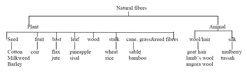
Natural fibres are derived from a number of organic sources, namely animals, fruit, mineral products or plants, all of which can be used as reinforcement as opposed to man-made elements, such as glass fibres. Notably, animal fibre sources include alpaca, camel, goat, llama and sheep, which can come in the form of hair, leather and wool; plant sources include abaca fibres, cotton, flax, hemp, jute, kenaf, lime, linen, ramie, sea grass and sisal. In addition, there are also fibres that can be sourced from insects, including silkworm cocoons [6, 24, 25 and 26]. Figure 9 shows natural fiber tree. More natural fibers are presented in Appendix F1, F1, F3 and F4.
1.3.1 History of Natural Fibres
The first composite material is known to have been made and used in Egypt approximately 3,000 years ago with the amalgamation of clay and straw, with the end product used to build walls. Since this time, fibres have been obtained from various sources in a number of different countries (see Table 2); however, with the passing of time, some materials are no longer used, although fibres are imported into Europe, including coir, hemp, jute, kapok and sisal, as well as those that may assist in the creation of cordage and clothes, and the erection of infrastructure [28, 29].
TABLE 2: FIBRES AND COUNTRIES OF ORIGIN.
| COIR | INDIA, SRI LANKA, MALAYSIA, PHILIPPINES |
| JUTE | India, Egypt, Jamaica, Ghana, Malwali, Sudan |
| SISAL | East Africa, Bahamas, Kenya, India, Tanzania |
| ABACA | Bolivia, Malaysia, Uganda, Philippines |
| FLAX | Borneo |
| HEMP | China, Yugoslavia |
| KENAF | Cuba, Togo, Jamaica, South Africa, Irag, Tanzania |
| SUN HEMP | India, Guyana, Nigeria |
1.3.2 Applications of Natural Fibres
Fabrics used in the case of both clothing and furniture are commonly made from natural fibres, with hemp recognised as being the preferred option in a number of industries owing to its low costs but high strength [30]. With this in mind, hemp fibres are used by Canadian suppliers as a reinforced fibre, which is subsequently utilised across a number of industries, including construction and the automotive sector, with further applications recognised owing to the fibre’s core strength and thus its appeal [31].
1.3.3 Advantages and Disadvantages of Natural Fibres
Overall, flexibility is known to be one of the main behaviour of natural fibre, with strength also a key element emphasising its suitability in terms of production and utilisation. In addition, it is known that natural fibres are renewable and are inexpensive, although it should nevertheless be acknowledged that the biodegradability and potential to cause skin irritation are some of the more pronounced disadvantages of the fibre [25]. In addition to those mentioned above, some of the advantages of utilising natural fibre as a composite reinforcement are noted as follows:
-A greater modulus weight ratio than other options, i.e. E-glass, meaning competitiveness in terms of stiffness-critical designs Structural Composite论文代写
-Environmentally friendly
-Lightweight construction potential [17].
-Lower costs than other options (namely E-glass and carbon fibres), (see Table3).
-Low energy consumption during production
-Lower natural fibre density than other options (namely E-glass and carbon fibre)
-Positive break behaviour
-Up to 50% lighter than glass fibres.
-The following are the recognised drawbacks of natural fibre as a composite reinforcement:
-Flammable material
-Incompatibility with some polymeric matrices
-Poor wet ability
-Significant problems in fibre-matrix interaction (reduces the mechanical characteristic)
-Variable quality
-Water absorption or expansion characteristics.
Markedly, the characteristics of natural fibre greatly depends on the way in which the sources have been grown in terms of air, environment, humidity, soil composition and temperature, to name a few. Such elements are known to impact the way in which a plant, for example, grows, i.e. the density and strength of fibre, and the height of the plant; this factor necessitates consideration [17, 20 and 25].
TABLE 3: COMPARISON BETWEEN NATURAL FIBRE AND GLASS FIBRE [68].
| PROPERTY | NATURAL FIBRES | GLASS FIBRES |
| Density | Low | Twice that of natural fibres |
| Cost | Low | Low but higher than NF |
| Renewability | Yes | No |
| Recyclability | Yes | No |
| Energy consumption | Low | High |
| Distribution | Wide | Wide |
| Health risk when inhaled | No | Yes |
| Abrasion to mechanics | No | Yes |
1.3.4 Natural Fibre as Reinforcement for Composites Structural Composite论文代写
There is a number of natural fibre types more commonly used as composite reinforcements. These are discussed below; Table4 shows properties of some natural fiber as reinforcement.
1.3.4.1 Flax:
Otherwise referred to as linen, flax has been used for several thousand years, and is nowadays utilised in the production of both cloth and paper [31]. The advantages associated with flax include its capacity to absorb humidity and thus enable the skin to breathe; its antistatic, antibacterial and low elasticity characteristics; and the fact that it is allergy-free. Moreover, fabrics made from flax do not change, and can therefore be washed without the product being affected [32]. Figure 10 shows flax fiber.
1.3.4.2 Hemp:
Hemp can be used to easily make a number of products and is notably simple to cultivate owing to its deep root system, which facilitates the plant in gaining access to and subsequently retaining water moisture, thus meaning irrigation is only minimally required. Moreover, hemp provides good yields owing to its dense foliage and height of 4–5 metres. During modern times, hemp is used in car manufacturing and textiles [30]. Figure 11 shows hemp fiber. Structural Composite论文代写
1.3.4.3 Jute:
Jute is known to grow in South Asia and is derived from the jute plant’s bark, and can be used as sea vessel cordage and ropes. It is widely acknowledged that jute has a multitude of uses, including the manufacture of packaging and carpets, although there is currently very little utilisation recognised across clothing sectors [33]. Figure 12 shows jute fiber.
1.3.4.4 Kenaf
This fibre is sourced from the bark and wood of Kenaf, with the bark (known as the bast) making up 40% of the entire plant. The Kenaf plant is cultivated for its fibre across a large number of locations, including parts of Africa, Bangladesh, Southeast Europe, Indonesia, Malaysia, South Africa, Thailand and Vietnam. Moreover, China and India are known to be key farming areas, with Mexico, Senegal and the USA also known grow the plant [34]. Figure 13 shows kenaf fiber.
TABLE 4: PROPERTIES OF SOME NATURAL FIBERS AS REINFORCEMENT [69].
| Properties | E-glass | Hemp | Jute | Coir | Cotton |
| Density g/cm3 | 2.55 | 1.48 | 1.46 | 1.25 | 1.51 |
| Tensile strength (MPa) | 2400 | 550-900 | 400-800 | 220 | 400 |
| E-modulus (GPa) | 73 | 70 | 10-30 | 6 | 12 |
| Specific (E/) | 29 | 47 | 7-21 | 5 | 8 |
| Elongation at failure (%) | 3 | 1.6 | 1.8 | 15-25 | 3-10 |
1.3.5 Mechanical Properties of Natural Fibre Composites Structural Composite论文代写
When considering the mechanical properties of fibres, this relates to a number of different aspects, including brittleness, ductility, elasticity plasticity, hardness, strength and toughness. Such properties are considered in regard to the stress or force the end products needs to endure and resist. With this in mind, compression, impact and tension are known to be common types of stress [19].
1.3.5.1 Impact property
It has been stated by some sources that hemp fibre incorporated within composite materials lessens the impact properties, with Liu et al (1999), for example, noting through their work that, when testing nylon-based composites, there was some reduction in the impact strength, decreasing from 20.6 J/m² to 18.1 J/m² following the incorporation of 4.7 wt% vinyl ester. On the other hand, however, Dhakal et al. [36], states that the opposite occurs, with hemp fibre impact properties increased following the incorporation of vinyl ester.
Impact testing provides some degree of insight into the way in which a certain element will react following stress burdens, which helps to ascertain whether or not the material can be considered brittle or tough, for example. Importantly, there are two main tests, namely Izod and Charpy tests, with the end result specified as energy in ft.ibs. Or KJ; this is necessary in order to break up the test piece [37]. Structural Composite论文代写
Another study by Sawpan et al. [37], also regarding mechanical properties of composites,
this time of hemp fibre reinforced polylactide (PLA) bio-composites, conducted tests to discover how to enhance the mechanical properties of reinforced PLA composites using chemically treated random short fibres and aligned long hemp fibres. Extrusion mixing and injection moulding were used to fabricate the short fibre, while compression moulding was used in the fabrication of the long hemp fibre. The fibre content wt. % started from (0-40). The weights used were 10, 20 and 30 wt.% fibre for the short fibre and 30, 35 and 40 wt.% fibre for the long fibre, respectively.
The results showed that with increased fibre reinforcement, the composites tensile and impact strength improved. On the other hand, fracture toughness was reduced. Furthermore, alkali and silane fibre treatments were used on the hemp fibre which had a positive effect on the tensile and impact properties because of increased matrix adhesion and crystallinity. The highest performing specimen was attained using 30 wt.% fibre reinforced PLA composites (with alkali treatment). The proceeding figure (1.F) highlights the comparison between hemp fibres, alkali treated fibres, silane treated fibres, alkali and silane treated fibres reinforced composites tensile properties [37].
Other studies have been conducted by Cantero et al. [38] which focussed on wettability and showed the mechanical behaviour of flax composites reinforced with polypropylene.
The study aimed to investigate different chemical treatments of composites and the method of fabricating these composites was extrusion mixing combined with injection moulding.
The ratio of fibre to resin matrix was a constant of 30 wt.%. There were two types of flax fibres used, which were natural flax and flax pulp and polypropylene composite. In addition to this, maleic anhydride (MA), maleic anhydride-polypropylene copolymer (MAPP) and vinyl trimethoxy silane (VTMO) were used as treatments for the fibre. Findings of this study showed that those composites that contained MAPP-treated fibres had the best outcome for mechanical properties, whereas the MA and VTMO-treated fibres produced results that were equivalent to the untreated specimens. Structural Composite论文代写
Dhakal et al. [36] studied the low velocity impact response of non-woven hemp fibre/unsaturated polyester (HFRUPE) composites.
The aim of the study was to compare impact results for E-glass fibre composites with the HFRUPE composite specimens. The fabrication method was hand lay-up with compression moulding. Impact tests were conducted on five specimens;
for UPE, 1-5 layers of hemp fibre reinforced specimens (which corresponded to fibre reinforcements of 0, 0.06, 0.10, 0.15, 0.21 and 0.26 volume fractions, respectively). The procedure was also conducted again with E-glass fibre reinforced composites specimens. Findings showed quantifiable increases in energy absorption and peak load with varying fibre volume fractions. The results of the experiment indicated that with fibre volume fractions increasing there was also increasing impact resistance properties. The best outcome was achieved with the hemp fibre reinforced composite of 21 wt.% fibre content, while the impact result at 21wt. % was similar to 21 wt.% of E-glass fibre composites [36].
More studies are presented in Appendix G.1 and G.2
1.3.5.2 Tensile property
With the use of suitable equipment, a standard test piece is secured in a testing machine. The machine gradually applies an axial pull, thus causing the stretching of the steel until breakage is experienced. This test provides insight into the elongation and reduction of area, proof stress, tensile strength, and yield point [36].
1.3.5.3 Flexure property
This particular test seeks to examine compressive, shear and tensile stresses acting in unison. Importantly, the test does not provide a key performance indicator of the material, and test data derived from one composite material cannot necessarily be compared with another. Essentially, the main aim of implementing such a test is for quality control purposes [51].
1.3.5.4 Water Absorption and its Effect on the Mechanical Properties
Water absorption refers to the amount of water absorbed by the composite material when immersed in water. It is known that, upon immersion and also in humid conditions, polymer
composites absorb water, which can cause the degradation of the fibre-matrix interface, thus causing a number of subsequent impacts, namely reductions in dimensional, electrical and mechanical properties [39]. Accordingly, it is recognised that water absorption is a critical consideration when utilising natural fibre as composite reinforces [4, 39, 40, and 41].
The effects of water absorption on the mechanical properties of hemp fibre reinforced unsaturated polyester composites have been studied by Dhakal et al. [4], whilst Akil et al. [40] considered water absorption in terms of pultruded hemp fibre reinforced unsaturated polyester composites. Moreover, in consideration to short jute fibre/polylactide composite in hygrothermal environment, Hu et al. [41] sought to assess microstructure evolution, moisture absorption and tensile strength. As was established through the course of the three aforementioned studies, three different mechanisms are known to govern moisture diffusion in the context of polymeric composites, namely:
1.the diffusion of water molecules inside the micro gaps between polymer chains
2.capillary transport into the gaps and flaws which interfaces between fibre and the matrix
3.Transport of microcracks in the matrix arising from the swelling of fibres (particularly in the case of natural fibre composites).
Accordingly, it is stated that the absorption-related behaviours illustrated can be assigned into one of several categories, as follows:
1.Linear Fickian behaviour: as a result of the moisture weight gain, equilibrium is gradually achieved following a rapid initial take-off.
2.Non-Fickian behaviour: moisture weight-gains fails to reach equilibrium following initial take-off. Structural Composite论文代写
3.Overall, in a composite, moisture diffusion depends on numerous aspects, including fibre voids volume fraction, humidity, temperature, and viscosity of matrix [4, 40 and 41].
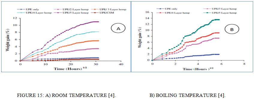
When conducting their study, the overall aim of Dhakal et al. [4] was to examine the impacts of moisture in regard to the mechanical properties of hemp/unsaturated polyester (HFRUPE) composites. In this context, the manufacturing approaches implemented for composite preparation included hand lay-up and compression moulding, with water absorption tests carried out by taking a number of specimens (0, 0.10, 0.15, 0.21, 0.26 fibre volume fraction specimens) and immersing them in a deionised water bath for different durations at two different temperatures, namely room temperature, i.e. 25oC, and boiling, i.e. 100oC.
An evaluation was carried out for both wet and dry samples using flexural and tensile tests, with results showing that,
upon the increase of fibre volume fraction, composite moisture similarly increased. Furthermore, flexural and tensile properties were found to decrease significantly owing to fibre-matrix interface degradation. The water absorption patterns of the composites can be seen in Figure 15, with A illustrating Fickian behaviours at room temperature and B displaying non-Fickian behaviours at elevated temperatures.
The study of Akil et al. [40] also carried the same aim as that of Dhakal et al. [4], although a different material (pultruded hemp fibre reinforced unsaturated polyester (HFRUPE) composites) was the target sample. During the course of this research, a thermoset Pultrusion machine was utilised for the preparation of the HFRUPE composites. Subsequently, absorption test were carried out, which involved the composite specimens being immersed into three conditions, namely acidic solution, distilled water, and sea water, all at room Temperature and for the same duration (three weeks).
Subsequently, it was established that non-Fickian behaviour patterns will illustrated, with the test results relating to compression and impact properties showing a decrease in mechanical properties with increased water uptake [40].
1.4 Matrix Structural Composite论文代写
‘Matrix’ is a term that can refer to a number of different materials; however, in the context of this study, the term relates only to polymeric system matrices.Polymer material is more commonly referred to as plastic, and is recognised as a long chain molecule comprising at least one repeating atom unit, adjoined through strong covalent links. Polymer matrix is the most widely used material in terms of composites, and can be broken down into two different categories, namely thermoset polymers and thermoplastic polymers [6, 14 and 42].
Markedly, matrices are utilised with fibre reinforcement in order to create composites materials for a number of reasons, including:
-To carry inter-laminar shear
-To control the chemical and electric properties.
-To deliver fibre surface protection from mechanical degradation.
-To hold fibres in place and thus transfer stresses between them.
-To provide a barrier against an adverse environment (minimise moisture absorption).
Every polymer matrix has different specific properties, all of which can be directed according to the structure and application aim, with the following providing good examples:
-To achieve low levels of shrinkage, thus facilitating the elastic properties in transferring load to the fibres.
-To achieve good levels of chemical resistance.
-To achieve strength at high temperature [14, 17, 22 and 43].
1.4.1 Types of Fibre (Resins Polymers)
The classification of polymers can be considered in terms of chemical family, molecular structure, or otherwise by the way in which they were made [22]. In regard to the molecular structure, classification is achieved by grouping the polymers into elastomers, thermoplastics and thermosetting plastics.
1.4.1.1 Thermoplastics:
A thermoplastic material is recognised as one that hardens following a heating and cooling process. Such plastics are made from branched or long linear chains, which are affixed together with the use of comparatively weak van de Waals bonds between atoms and chains. Notably, such materials are easily heated, processed and pressed into shapes. Injection moulding makes use of such application. Figure 16 shows thermoplastic structure. Structural Composite论文代写
One advantage of thermoplastics can be seen when considering their easy reformation upon heating, which thus facilitates recycling; however, in contrast, the material degrades during such heating processes.
The most well-known thermoplastic is Polyether Ether Ketone (PEEK), which is a linear aromatic thermoplastic based on the repeating unit of Ketone-Ether-Ether. Markedly, upon slow cooling from melting point, PEEK crystallinity can vary from amorphous up to achievable crystallinity of 48%. Importantly, however, the process is expensive, although this is a drawback commonly overlooked when high-performance is a prerequisite, such as in electronic and transportation industries, wherein high-temperature applications with continuous fibres metallic are apparent [44].
1.4.1.2 Thermosets:
Thermosetting plastics are made up of branched or cross-linked chains, subsequently forming a three-dimensional network arrangement. Through the use of heat, the polymer hardens, subsequently producing a cross-linked formation. Upon the hardening or ‘curing’ or a thermoset, the application of heat will not result in any softening owing to the structural constitution whereby the molecular motion of the polymer is constrained by the cross-links. Importantly, if temperatures are excessive, thermosets are known to char and decompose. Structural Composite论文代写
However, thermosets do not dissolve, whilst thermoplastics will if exposed to the right solvent [46].When considering a comparison between the two, it is recognised that a greater degree of brittleness, strength and stiffness are exhibited by thermosets. However, fewer processing approaches are available, with thermoset shapes determined by their establishing mould, with changes or manipulations to a cured thermoset only achievable through machining.
With this in mind, one of the main drawbacks of thermosets is the recycling difficulty owing to the incapability of such materials to soften when exposed to heat.
There is also the availability of vinyl ester, which is a resin made from epoxy with unsaturated monocarboxylic acid. Notably, this particular combination facilitates the dissolve of the reaction product in a reactive solvent, and may be used as a substitute for epoxy and polyester, with vinyl ester recognised as being low in viscosity [45]. Figure17 shows thermoset structure. Table 5 shows a comparison between thermoset and thermoplastic.
Advantages of vinyl ester:
-Excellent chemical resistance
-Excellent tensile strength
-Fast curing
-Good adhesion
Disadvantages of vinyl ester:
-High volumetric shrinkage (5–10%).
-Polyester belongs to the polymer group and therefore comprises ester. This type of polyester is known to have virtually the same elements as polyethylene terephthalate, constituting naturally occurring chemicals.
Advantages of Polyester:
-Crease-resistant
-Excellent wash-wear performance
-Good levels of strength
-Maintains creases and heat set plates.
Disadvantages of Polyester:
-Absorbs body oil
-Accumulates static electricity
-Melts if exposed to high temperatures. Structural Composite论文代写
–Epoxy is a type of resin, which becomes clear upon heating. This material is predominantly used in the aerospace industry, and is recognised as being useful in terms of improving overall structural matrix material and also as a structural glue.
TABLE 5: COMPARISON BETWEEN THERMOPLASTIC VS THERMOSET [70].
| PROPERTY | THERMOPLASTIC POLYMER | THERMOSET POLYMER |
| Formulations | simple | complex |
| Fabrication cost | Low | High |
| molecules | not joined together | joined together |
| reshaped | Can be | Can`t be |
| Melt viscosity | high | Very low |
| Heat soften | Can be | Might burn if heat-softened but possible |
stiffness |
increases after curing | increases after curing |
| Thermal stability | Less | Better |
| Creep and stress relaxation | Higher | Lower |
| chemical resistance | Less | Better |
| storage life at room temperature | Unlimited | Limited |
| fabrication time | Shorter | Longer |
| recycling | Can be | Can`t be |
| Impact strength | High | Low |
| strain-to-failure | Higher | Low |
| Environmental durability | Unknown | Good |
| Database | Small | Very large |
1.4.1.3 Elastomers:
Elastomers are commonly thermosetting plastics comprising a low level of cross-link density, thus illustrating very distinguishing characteristics [49]. Notably, when exposed to keen levels of stress, elastomers may exhibit double-sided strain [47] for example, upon the application of a force, deformation may be experienced; however, upon the removal of such a force, the original shape of the elastomer will be resumed, with such elastomers able to endure elastic deformation of in excess of 200% [48]. With this in mind, it may be stated that thermoplastic elastomers are a special elastomer comprising a number of different elastomer behavioural properties alongside the processing capabilities exhibited by thermoplastics. Figure 18 shows elastomers structure. Structural Composite论文代写
1.5 Manufacturing Process of Composites
Overall, manufacturing processes should be carried out in the same way when combining matrix and reinforcing materials, namely through combining and compacting the materials and accordingly processing them through melding, during which the shape is set. The various different types of composite may be manufactured in the same way but may constitute different situations. For instance, the meld event in the case of the thermoset matrix is when chemical reactivity or heat is added [50]. Markedly, the process is commonly carried out at ambient atmospheric pressure and temperature, although there are a number of different fabrications, as discussed below.
1.5.1 Hand Lay-up
- Cairns and Jon D. Skramstad et al [65], have studied the evaluation of hand lay-up method and RTM on the composite wind turbine blade, and they stated that Hand lay-up method has generates a textured finish on the inner surface of the blade skin that reduce the bonding between parts. On the other hand, this method offers the advantage to construct large complex parts with quick set up time at reasonable coast. In the context of composites fabrication, the hand lay-up approach is the oldest, utilising open moulds to create the composite shape. The process is implemented as follows:
1.The mould shape is selected and the fibre mats cut in consideration to the mould dimensions.
2.There may be the application of the polymer release agent at this point.
3.The mixture of resin/catalyst is poured into the mould, with the fibre mats placed onto it.
4.Hand rollers are used to squeeze the resin inside the resin/fibre layers and to remove any trapped air. Structural Composite论文代写
5.The design requirements are conducted to establish the amount of resin, the number of layers, and the thickness of the composite to be produced.
6.Curing is speeded up through the application of evaluated heat to the composites, although room temperature can also cure the resin.
7.The fibre-reinforced polymer composite is taken out of the mould.
Finishing actions may be implemented at this point. Figure 19 shows hand lay-up process.

1.5.2 RTM
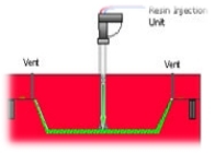
S.Cairns and Jon D. Skramstad et al[65] have stated in their study about wind turbine blade structures that RTM process is major potential in wind turbine blade structure as it is capable to produce complicated geometries. They conclude that RTM is more economically than traditional methods.
RTM processes make use of two different mould sets on either side of the panel: on the upper side there is either a flexible or rigid mould, which notably depends on the function; on the lower side, on the other hand, the mould is rigid. Both moulds fit together with a cavity in between, which facilitates the improvement of the resin transfer moulding: the materials are inserted into the cavity and the mould set is closed, at which point the matrix material is added [50]. Figure 20 shows RTM process.
1.5.3 Compression Moulding Structural Composite论文代写
Park.C.H et at [66] has examine the mechanical and physical response on the fibre orientation state and the fibre contents distribution in compression moulding. Through the compression moulding, the pressure varies parabolic ally with the distance from where it will be shorter in case of circular pre charge. This approach is utilised during the process of manufacturing composite parts, and is most commonly implemented through the design of moderately curved parts or larger flat parts, such as those displayed in Figure 20. Such an approach is adopted in combination with thermoset resins, although it is acknowledged that it can also be implemented when processing thermoplastic resigns, i.e. fibre-reinforced thermoplastics [50].
Compression moulding is carried out as follows:
1.The materials are inserted into the mould cavity.
2.The mould is closed by a hydraulic ram under a heat plate.
3.Heat and pressure are applied until curing occurs and the bulk mould conforms to the mould shape then the mould is left to cool. After that, the parts are removed. Figure 21 shows compression moulding. Manufacturing process types are presented in Appendix H1, H2, H3, H4, H5 and H6.
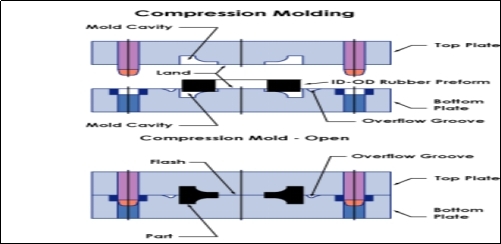 FIGURE 21: COMPRESSION MOULDING [71].
1.6 Summary of literature review Structural Composite论文代写
Composites types and its classification have been studied in order to gain knowledge of what composites are and how they are categorized. There are three different types of composites materials as mentioned in section 2.1.2. Figure 2 shows the structure of composites.
In addition, natural fibres were considered in section 2.3. Natural fibres are derived from a number of organic sources, namely animals, fruit, mineral products or plants, all of which can be used as reinforcement as opposed to man-made elements, such as glass fibres. Notably, animal fibre sources include alpaca, camel, goat, llama and sheep, which can come in the form of hair, leather and wool; plant sources include abaca fibres, cotton, flax, hemp, jute, kenaf, lime, linen, ramie, sea grass and sisal. Following on from this, the manufacturing processes of composites materials have been studied and investigated in section 2.5 and appendix H.1-6.
Matrices section 2.4 includes epoxy resins, bismaleimide resins, polyimide resins, and thermoplastic resins which have been explained as well.
It is seen that the mechanical properties of composites usually depend on the composite’s structure. This means that these properties are typically dependent on the shape of inhomogeneities, the volume fraction occupied by the inhomogeneities, and the interfaces between the constituent components. The strength depends on factors such as the brittleness or ductility of the inclusions and the matrix.
The main objective of this project is to investigate and study the effect of water absorption on the mechanical properties (impact and flexure) of jute fiber composites. Chapter 3 includes the materials and processes that have been used in order to fabricate the composite as well as the test producers and parameters for both impact and flexure test. Chapter 4 includes the experimental results. These results are discussed in section 4.1- 4.6. Finally, chapter 5 includes the conclusion of the experimental results.
2 References:
[1]Environmentally friendly.(n.d.). Retrieved February 20, 2012, from Wikipedia: http://en.wikipedia.org/wiki/Environmentally_friendly [2]Smith, S. (2012, February 12). What is Eco-Friendly?Retrieved from Wise Geek: http://www.wisegeek.com/what-is-eco-friendly.htm [3]Wambua, P., Ivens, J., & Verpoest, I. (2003). Natural fibres: can they replace glass in fibre reinforced plastics? Composites Science and Technology, 1259-1264 [4]Dhakal, H. N., Zhang, Z. Y., & Richardson, M. O. (2007). Effect of water absorption on the mechanical properties of hemp fibre reinforced unsaturated polyester composites. Composites Science and Technology,1674-1683. [5]Bledzki AK, Gassan J. Composites reinforced with cellulose based fibres. Prog Polym Sci 1999;24(2):221–274. [6]Hepworth DG, Hobson RN, Bruce DM, Farrent JW. The use of unretted hemp fibre in composite manufacture. Composites: Part A 2000;31:1279–83.[7]Bruijn JCMD. Natural fibre mat thermoplastic products from a processor’s point of view. Appl Compos Mater 2000;7:415–20.
[8]Poling, A. & Normand, M. (1999). Noncontingent reinforcement: an inappropriate description of time-based schedules that reduce behavior. Journal of Applied Behavior Analysis, 32, 237–8 Structural Composite论文代写 [9]Daniel I. M., I. O. (2006). Engineering Mechanics Of Composite Material.Oxford: Oxford University Press. [10]Strong, B. (2006). History of composite materials– opportunities and necessities. brigham young university, 8. [11]Johnson, T. (n.d.). History of Composites. Retrieved February 20, 2012, from About.com:http://composite.about.com/od/aboutcompositesplastics/a/HistoryofComposites.htm [12]Haibin Ning, U. V. (2007). Design, manufacture and analysis of a thermoplastic composite frame structure for mass transit. Composite Structures, 105-116 [13]Zhao and J. Gou (2009). “Improved fire retardancy of thermoset composites modified with carbon nanofibers.[14]Matthews F. L., R. R. (1994). Composite Materials: Engineering and Science.Oxford: CHAPMAN AND HALL.
[15]Andrew Cripps, I. L. (2002, March 8). New report highlights the advantages of fibre reinforced polymer composites. Retrieved from Buro Happold: http://www.burohappold.com/BH/NWS_2002Newreporthighlightstheadvantagesoff.aspx [16]Bannister, I. H. (1998). The manufacture of glass/epoxy composites with multilayer woven architectures. Composites Part A, 293-30 [17]Mallick, P. (2008). In P. Mallick, Fibre-Reinforced composites, materials, manufacturing and design(pp. 1-117). London: Taylor and Francis Group. [18]Jones, R. M. (1999). Introduction to composite materials. In R. M. Jones, Mechanics Of Composite Materials(pp. 1-53). Philadelphia: Taylor & Francis. [19]Ii Maries, B. Abderrahim, L. Umadevi, I.L. Laurent, T. Sabu, 2006. mechainical properties. Thermophysical properties of naturalfiber reinforced polyester compositesComposSci Technol, p. 2719–2725. Structural Composite论文代写 [20]Rijswijk K., B. W. (2003). Application of Natural Fibre Composites in the Development of Rural Societie..Retrieved from FAO corporate document repository: http://www.fao.org/docrep/007/ad416e/ad416e00.htm[21]Matthews F. L., R. R. (1994). Composite Materials: Engineering and Science.Oxford: chapman and hall.
[22]Schawartz, M. (1997). Composite Material Processing, Fabrication and Application.New Jersey: Prentice Hall PTR. [23]Hollaway, (1993) L polymer composites for civil structure, London. [24]By Newell, James,2009 essential modern of Materials scienceand engineering, Hoboken, N.J. : John Wiley 2009 [25]Jorg Mussig, C. S. (2010). Industrial Applications of Natural Fibres: Structure, Properties and Technical Applications.Chichester: John Wiley and Sons. [26]Natural Fibre.(n.d.). Retrieved: januery 15, 2012, from Wikipedia: http://en.wikipedia.org/wiki/Natural_fibre [27]Binhai, T. (n.d.). Natural Plant and Animal Fibres – A return to renewable resources. Retrieved January 18, 2012, from Natural Fibres :http://www.binhaitimes.com/[28]Bledzki, A. K., Reinhmane, S. and Gassan, J.Thermoplastics reinforced with wood fi llers. Polym Plast. Technol. Eng. 1998;37:451-468
[29]Marion, P., Andréas, R. and Marie, H.M.. Study of wheat gluten plasticization with fatty acids. Polym.2003; 44:115-122. [30]Mwaikambo, L.Y. and Ansell, M.P.. Hemp fibre reinforced cashew nut shell liquid composites Compos. Sci. Technol. 2003;63:1297-1305. [31]Jiang, L. and Hinrichsen, G.. Flax and cotton fibre reinforced biodegradable polyesterDie Angew. Makromol.Chem. 1999;268:13-17. [32]Sultana C. 1992. Scutcing of retted-flax straw. In: The Biology and Processing of Flax 575 p. (Sharma H.S.S; Van Sumere C.F. ed.). M Publications, Belfast. p. 263 [33]Santulli and W.J. Cantwell, Impact damage classification of jute fibre reinforced composites, J Mater Sci Lett 20 (2001), pp. 477–479. Full Text via CrossRef | View Record in Scopus | Cited By in Scopus (7). [34]Aziz S. H., Ansell M. P.: The of alkalization and fibre alignment on the Mechanical and thermal properties of kenaf and hemp bast fibre composites: Part 1 – polyester resin matrix. Composites Science and Technology.2009; 64, 1219–1230[35]Glass fibre reinforced plastics-tensile test. BS EN 1998;2747:1-11
[36]Dhakal H, Z. Z. (2007). The low velocisty impact response of the non-woven hemp fibre reinforced unsaturated polyester composites. Composite structure , 559-567. Structural Composite论文代写 [37]Sawpan M, P. K. (2011). Improvement of mechanical performence of industrial hemp fibre reinforced polylactide biocomposites. Composites, 31-319. [38]Cantero G, A. A.-P. (2003). s of fibre treatment on wettability and mechanical behaviour of flax/polypropylene composites. Composites Scince and Technology, 1247-1254. [40]Water absorbtion. (n.d.). Retrieved januery 14, 2012, from Integrated Publishing: http://composite.about.com/library/glossary/w/bldef-w6012.htm [41]Akil H, W. L. (2009). Water absorption study on pultruded jute fibre reinforced unsaturated polyester composites. Composites Science and Technology, 1942–1948.[42]Hu R, S. M. (2010). Moisture absorption, tensile strength and microstructure evolution of short jute fibre/polylactide composite in hygrothermal environment. Material and Design, 3167-3173.
[43]Ratti, A.; R. Gough, M. Hoff, R. Keller, K. Kennedy, R MacGill, J. Staples (1999). “The SNS RFQ Prototype Module [44]Eckold, G. (1994). Design and Manufacture of composite structure.Manchester: Woodhead Publishing Ltd. [45]Alger, M. S. M., (1989). Polymer Science Elsevier Applied Science. 1851662200. 477. [46]Carley, J. F., (1993). Whittington’s Dictionary of Plastics(3rd ed.). Thechnomic Publishing co. inc. 1566760909. [47]Nicholson, J. W. (1991). The Chemistry of Polymers. The Royal Society of Chemistry. 0-85186-413-9. 14 [48]Bolton, W. (1998). Engineering Materials Technology(3rd ed.). Oxford: Butterworth-Heinemann. 0750639172.141[49]Askeland, Donald R. (2004). Essentials of Materials Science and Engineering (4th ed). Brooks/Cole. 0534253091. 672.
[50]Young, R. J. (1991). Introduction to polymers(2nd ed.). London: Chapman and Hall. 0412306301. 10. Structural Composite论文代写 [51]G. Advani and Murat Sozer “Process Modeling in Composite Manufacturing”,Marcel Dekker, Inc., 270 Madison Ave., NY, NY 10016, ( 2002). [51]Adams, D. D., 2008. flexural testing of fiber-reinforced ceramices. [Online] [52]Available at: http://www.compositesworld.com/articles/flexural-testing-of-fiber-reinforced-ceramics Accessed 31 march 2012. [53]Gu, H.,Dynamic mechanical analysis of the seawater treated glass/polyester composites, Materials and Design (2008) (Accepted Manuscript) [54]shori, A., and Sheshmani, S. (2010). “Hybrid composites made from recycled materials: Moisture absorption and thickness swelling behavior,”Bioresource Technology, 101(12), 4717-4720. [55]Ahmed, K. S., and Vijayarangan, S. (2007). “Experimental characterization of woven jute-fabric-reinforced isothalic polyester composites.” Journal of Applied Polymer Science, 104(4), 2650-2662.[56]Kiani, H., Ashori, A., and Mozaffari, S. A. (2010). “Water resistance and thermal stability of hybrid lignocellulosic filler-PVC composites,”Polymer Bulletin 1-6 (DOI:10.1007/s00289-010-0381-z).
[57]Pothan, L. A., Cherian, B. M., Anandakutty, B., and Thomas, S. (2007). “Effect of layering pattern on the water absorption behavior of banana glass hybrid composites,” Journal of Applied Polymer Science 105(5), 2540-2548. [58]Mariatti, M., Jannah, M., Bakar, A. A., and Khalil, H. P. S. A. (2008). “Properties of banana and pandanus woven fabric reinforced unsaturated polyester composites,” Journal of Composite Materials 42(9), 931-941. [59]Yang, H.-S., Kim, H.-J., Park, H.-J., Lee, B.-J., and Hwang, T.-S. (2006). “Water absorption behavior and mechanical properties of lignocellulosic filler-polyolefin bio- composites,”Composite Structures 72(4), 429-437. Structural Composite论文代写 [60]p. Wambua, J. Ivens and I. Verpoest, “Natural fibers: can they replace glasss in fiber reinforced plastic?,” Composites Science and Technology, vol. 63, 2003, pp.1259-1264. [61]p. Wambua, J. Ivens and I. Verpoest, “Some mechanical properties of kenaf/pp composites prepared using film stackicng technique,” In:13thinternational conference on composite materials conference proceedings, 2001, pp.25-29. [62]jack R. Vinson, R. L. Sierakowski The behavior of structures composed of composite materials [Book]. – Dordrecht, Netherlands : Springer, 2002.[63]Biswas, S., Mittal, A. & Srikanth, G. 2002. Composites: A vision for the Future. Proceeding of the international Conference &exhibition on reinforced Plastics ICERP IIT Madras.
[64]Tani, Y. 2002 Tensile and transverse strength of composites after measuring in water. http://iadr.confex.com/iadr/2002SanDiego/techprogram/abstract_15832.htm Retrieved on 29 June 2012. [65]Umair, S 2006, ‘Environmental impacts of fiber composite materials’, Masters Thesis, Stockholm University, accessed 27 January 2008 from Lightweight Construction Applications at Sea Reports Database. [66]Skramstad J D.(1999). Evaluation of hand lay-up and resin transfer molding in composite wind turbine blade manufacturing.pp.1/10. [67]Park C H, Lee W I. (2001). A study on fibre orientation in the compression molding of fibre reinforced polymer composite material. Material processing Technology, 233-239. Structural Composite论文代写 [68]Reinforcement Properties for Composite Materials Reinforcement properties for composite materials(n.d). Retrieved on January 13, 2012: http://www.azom.com/article.aspx?ArticleID=978. [69]Edgars Sparnin.(2006).Mechanical properties of flax fibres and their composites.division of polymer engineering, 1402-1757.[70]Richard P. (2005).Bio-based polymers and composites.
[71]Zhang, Z Y. (2011).Material and manufacture, lecture notes distributed in introduction of compositesat The University of Portsmouth. [72]Kopeliovich,D.(n.d).compression moulding .retrieved march 15,2012 from : http://www.substech.com/dokuwiki/doku.php?id=compression_molding_of_polymers [73]Rahman R, H. M. (2008). Improvement of physico-mechanical properties of jute fiber reinforced.Composites , 1739-1747. [74]Moneiro S, T. L. (2008). Mechanical performance of coir fibre/polyester composites. Polymer Testing , 591-595.3 Appendices Structural Composite论文代写
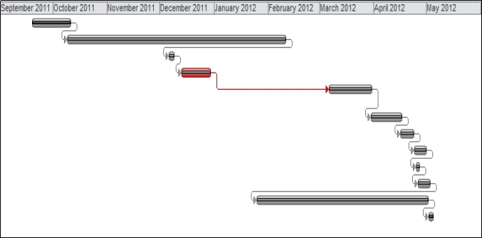
| Task Name | Duration | Start | Finish | % Complete |
| Data collection | 16 days | Mon 19/09/11 | Mon 10/10/11 | 100% |
| Literatures review | 90 days | Sun 09/10/11 | Fri 10/02/12 | 100% |
| Samples fabrication at university laboratory | 3 days | Tue 06/12/11 | Thu 08/12/11 | 100% |
| Break | 13 days | Tue 13/12/11 | Thu 29/12/11 | 100% |
| Water immersion of specimens in sea water at RT -Without weekends- | 19 days | Tue 06/03/12 | Fri 30/03/12 | 100% |
| Impact tests for wet specimens & discussion | 12 days | Fri 30/03/12 | Mon 16/04/12 | 100% |
| Flexural tests for dry specimens & discussion | 6 days | Mon 16/04/12 | Mon 23/04/12 | 100% |
| Review discussion and conclusion | 5 days | Tue 24/04/12 | Mon 30/04/12 | 100% |
| SEM images | 2 days | Wed 25/04/12 | Thu 26/04/12 | 100% |
| Poster preparation | 5 days | Thu 26/04/12 | Wed 02/05/12 | 100% |
| writing final report | 70 days | Wed 25/01/12 | Tue 01/05/12 | 100% |
| Organizing final report & Submission | 3 days | Wed 02/05/12 | Fri 04/05/12 | 100% |
3.5 Appendix E.1
Mechanical Behaviours of Composite Materials
The main reason for manufacturing composite materials is to make sure that composites used have positive qualities, and to avoid ones with negative properties. One major aim is to find composite materials which are capable of bearing heavy loads. The composite materials must be carefully designed and must have the appropriate component materials to have a proper load-bearing capacity.
This can only be achieved if the mechanical behaviour of the materials, including the pattern deformation of the material when it is bearing mechanical loads, is studied. Characteristics of materials relevant to fractures such plasticity, elasticity, creep, fracture, and fatigue provide the information needed about these materials’ behaviour. Studying mechanical behaviour also allows us to grasp the physical processes that are occurring in the materials when they are subjected to loads, and understanding these processes allows us to determine which procedures should be used to make the material stronger [61].
3.6 Appendix E.2
Characteristics of Composites: (continue for section 2.1)
The strength of composites is a key characteristic of composites. Because they are very hard and rigid, they are strong but they also have a low weight, and can be used for buildings and ships. Their tensile strength (the capacity to bear stress) measures four to six times more than that of steel or aluminium [62]. Structures of composites weigh 30 – 40% less than if they had been made of aluminium. Composites’ great strength, their low weight and their superb design flexibility mean that they are very suitable for structures with these requirements [63]. Environmental interaction may however affect the strength of composites, with a recent study demonstrating a lower level of tensile and transverse strength in composite resins because of water absorption after they had been stored and tested in water rather than in dry conditions [64]. Structural Composite论文代写
Natural fibre: (continue for section 2.3.4)
There are a range of natural fibres that can be used to make a composite or as constituent fibre for a composite material. As illustrated in figure 1, cotton grows naturally from plants. It is one of the most well known and most used fibre for making textile material for clothing, garments etc.
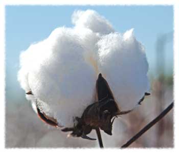
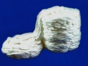
However, if picked by hand the work is laborious , and on a large scale an automatic system with machines is used. The picked ‘cotton wool’whereas the cotton is baled, any debris such as seeds, dead leaves and insects are separated through by ginning. After the cotton is clean it is baled again and is now ready for being spun. Unlike some other natural fibre, cotton is much weaker. Although a quality of cotton is that is absorbs moisture up to as much as 20% of its dry weight, without getting damp and another property is conduction of heat.Apart from clothes, cotton is also useful for manufacturing carpets, blankets, mops and medical-grade cotton wool.
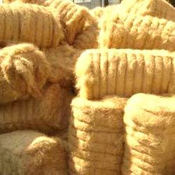
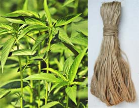
Another very useful natural fibre is called coir, the collected fibre as seen in Figure 40 is plentifully harvested from coconut husks.
This is despite the size of coconut palm trees reaching some 20 metres in height again making work to collect the fibre challenging and intensive. Sometimes monkeys can be trained to climb the trees to pick them, or people will climb or use a type of pole with a blade attached. Structural Composite论文代写
After dehusking and retting, the fibres are then collected by being beat and washed. Coir fibres are strong, light and easily with heat tolerance and resistance from salty water. Following growth of nine months, coconuts remain green and still contain white fibre useful in making yarns, ropes and fishing nets. Within twelve months of growth, the fibres become brown and may still be useful for brushes and mattress material.
3.7 Appendix F.2
Next, the ramie plant is a good producer of fibre which again is often collected by hand. It is a plant best suited to the tropics. However, the retting process that follows requires chemicals because of a gum-like substance around the fibres, which is necessary to extract.

The retting process is costly and controlling the process is not an easy task meaning that fibres may get damaged as a result. On the other hand, the fibre is highly durable and can be dyed so is invariably useful for decorative fabrics instead of construction material. This includes curtains and wallpapers, as well as sewing threads and even furniture covers. As shown in Figure 43, another natural fibre is jute, which has a wide range of use, although it is one of the weakest types of stem fibre. Jute is obtained from the bast or skin of the plant stem. It is one of the next most valuable types of natural fibre after cotton, being widely available and in constant demand.
It has a high level of tensile strength, as compared to other natural fibres, being versatile and one of the best fibres to make top quality yarn, cords and twine from, in addition to sacks and materials for packaging and wrapping.
Moving on to a different plant that produces another natural fibre, flax (pictured in Figure 43) produces a valuable fibre useful as an alternative composite form in the filtration industry.
Some of the many good properties of flax fibre are that it is anti-static, has low elasticity, while it is also durable and has good tensile strength. Like cotton, it is also washable although flax fibre does not easily lose its shape.In addition to those properties mentioned above flax has good absorbency properties, regarding water retention as well as heat and conductivity. It is useful in the fabrication of Sports equipment and for use in wind energy research. Some other applications of the material are in covers, and environmentally-friendly packaging.One other type of fibre that come from plant origin is mostly known for its connection to narcotic use.

3.8 Appendix F.3
Despite this connection by name only, hemp fibre has little or no connection to the drug taking and illegal smuggling trade.
The plant grown for its fibre is not chemically the same as the variation used to make the drug, and except for some strict laws that ban all plants of this type, hemp is generally cultivated legally to obtain the fibre which it produces, a type of fibre which has good absorbency and is not easily damaged by water, which can also be dyed, while at the same time it is strong and durable, and has qualities of softness and lustre. It can be used in place of wood and as an eco-friendly alternative fibre, useful also in construction, for insulating.
Major natural fibres of vegetative origin
TABLE 9: MAJOR NATURAL FIBRES OF VEGETATIVE ORIGIN USED AS REINFORCEMENT.
| Fibre | Type |
| Bagasse | Cane |
| Bamboo | Grass |
| Banana | Stem |
| Coconut husk | Fruit |
| Flax | Bast |
| Hemp | Bast |
| Jute | Bast |
| Kenaf | Bast |
| Sisal | Leaf |
| Wood | Stem |
Overall, there are many advantages for using natural fibre to make reinforced composites, including lower levels of energy consumption, good elasticity meaning complex shapes can be formed, decreased density and as a result of using natural fibre instead of carbon reinforcements, this also makes the material light-weight and durable fabric, being tough with comparative strength and stiffness to glass-type reinforcements.
3.9 Appendix F.4
Finally there are other advantages available when natural fibre is used including the ability to reuse and recycle unused parts such as waste cuttings when the material is used in moulding and manufacturing processes. The natural fibre used to fabricate composites is also considerably safer than other reinforcements such as glass and has less risk of causing harm or injury when involved in the manufacturing of composite materials. While another point in favour of natural fibres is that they are also compostable and totally biodegradable.
However, turning to the disadvantages of natural fibre in fabrication of composites, the fibre may not always be of the same quality,
as cultivation and origin can change the properties of natural fibres, resulting in many variations. In addition, the economic conditions of workers and the labour-intensiveness, as well as being dependent on time, seasons and weather, can make natural fibres difficult to rely on compared to mechanical and man-made fibres. Structural Composite论文代写
Another disadvantage is the amount of compatibility when using natural fibres as a composite reinforcement, when normally the matrix and fibres have to be compatible, incompatibility is a problem. This may be caused by moisture damage or high water absorbency of natural fibres, making the reinforcement material lose its original shape, similarly, being flammable or having low resistance to ultra violet radiation can also lead to degradation of the fibre and composite. Summing these all up, these factors can also cause changes for the price and economic output may go up or down, based on the supply and demand, during cultivation and production.
3.10 Appendix G.1
According to a study by Monteiro et al. [73] in which the ratio of fibre and resin mix was changed in order to investigate the mechanical properties of coir fibre and polyester reinforced composites, when the fibre content wt% is up to 50, rigid composites were obtained. The method used to fabricate the composites was compression moulding.
In addition, different moulding pressures were used during the preparation of the specimens using varying amounts of coir fibre with up to 80 wt%. Those composites that had a higher value of fibre content wt% than 50 preformed as more flexible agglomerates. The orientation of loose coir fibres for this experiment was random, while both tangled and matted forms of the fibre were used. It was concluded that coir fibre polyester reinforced composites can be fabricated with flexural strength which makes them useful for non-structural building purposes. Figure 9 shows the strength variation with the amount of coir fibres for the composites fabricated at the two moulding pressure levels [73].
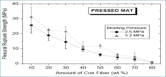
Figure 46: VARIATION OF THE FLEXURAL STRENGTH WITH THE MASS FRACTION OF COIR FIBRES AND MOULDING PRESSURE FOR PRESSED MAT [73].
3.11 Appendix G.2 Structural Composite论文代写
As reported by Rahman et al. [72] while studying the improvement of physico-mechanical properties of jute fibre reinforced with polypropylene composites having post-treatment, raw and oxidized specimens were made using the methods of extrusion mixing and injection moulding. Post-treatment of the composites was carried out with urotropine. Moreover, using
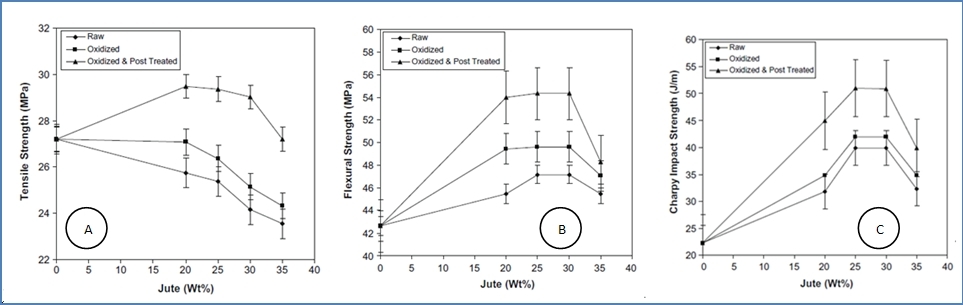
FIGURE 47: VARIATION OF A) TENSILE STRENGTH, B) FLEXURAL STRENGTH AND C) IMPACT STRENGTH AT DIFFERENT FIBRE LOADING SHOWING POSSIBLE DATA TREND [72].
the following weights of jute fibre; 20, 25, 30 and 35 wt.% they learnt that the mechanical properties improved with post-treatment specimens when compared to the raw and oxidized samples.
Those composites that were 30% fibre reinforced produced the optimum results. The conclusion reached was that the polypropylene matrix and urotropine required better and stronger bonding which was produced with treated jute fibre, for the mechanical properties to be improved with higher fibre content.
Another observation was that following shock loading of the jute fibre there was a reduction of tensile strength in the composites. Despite this, composites have 20% higher tensile properties than raw and oxidized samples; in addition flexural and impact properties improved with increasing increments of loading leading to an improvement on the results of both raw and oxidized specimens. The differences of mechanical properties at various fibre-loads are indicated in Figure 10, below [72].
3.12 Appendix H.1
Manufacturing processes: (continue for section 2.5)
The methods used to make composites can be divided simply between open molding and closed molding. The difference is that open molding is left exposed after gel and laminate are applied, whereas for closed molding, the composite is placed into either a vacuum bag or a two-sided mold set. Structural Composite论文代写
From this we can see a range of processing techniques, using mostly closed molding, including pultrusion, compression molding, vacuum bag molding and vacuum infusion processing, centrifugal casting and continuous lamination, in addition to reinforced reaction injection molding (RRIM) and resin transfer molding (RTM). The manufacturing process chosen depends on certain factors such as cost, quantity, materials and size. Open molding techniques include hand lay-up, spray-up and filament winding.
For small quantities of production, where the composite is low in production volume, hand lay-up or vacuum molding and processing methods will be suitable.
Whereas for increased volumes, filament winding, centrifugal casting, compression molding and RTM will be better. On the other hand, for large scales of production at high volumes, pultrusion, continuous lamination and RRIM will be used.
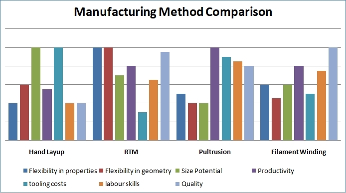
FIGURE 48: COMPARSION OF MANUFACTURING PROCESS METHODES
3.13 Appendix H.2
- Open Molding:
1.Hand Lay-Up ( has been discussed in section 2.5.1)
The molds used in hand lay-up are simplified, single-cavity molds of usually made of fibreglass. The molds can vary in size, and could be very small or even very large, and overall are not very costly in the scale of molds used to manufacture composites.
2.Spray-Up (Chopping)
Spray-up (Fig. 7), in particular, also called chopping, is an open mold method similar to hand lay-up which is useful for making boats, tanks and other components as well as bath and shower units, in many shapes and sizes. The advantage of using chopped laminate is the conformability and because sometimes it can be faster than hand lay-up when molding complex and intricate shapes.
With the method of spray-up, an operator has the ability to control the process and factors such as thickness are more consistent. Although this means the work is also more dependent on skilled operators than with hand lay-up. Perhaps the volumes of production per mold may be relatively low, yet a substantial increase in production can be made by using multiple molds.
The process begins like the hand lay-up method, in that an application of gel is added to the mold prior to using the substrate laminate during spray-up.
A chopper gun ensures a continuous roving glass strand and catalyzed resin are fed out and deposited onto the resin-saturated “chop” of the mold. The glass strands are then thoroughly saturated by the rolling of the laminate and to compact the chop. To improve or increase the thickness, additional layers of chopped laminate can be added. Furthermore, woven roving or knitted fabrics as well as other roll stock reinforcements are available for use with the chopped laminates. Again as part of this process, core materials of the same type used during hand lay-up can also be integrated. Structural Composite论文代写
3.14 Appendix H.3
3.Filament Winding
The mold is configured to produce a finished inside layer and a surface laminate on the outside. Filament winding as illustrated in figure 8, has good results in terms of providing high tensile strengths when hollow and cylindrical products are manufactured due to a high degree of fibre loading. The work is done by using a roving filament that goes through a resin bath and is then wound around the revolving mandrel, often made of steel or aluminum.
The roving feed is carried by trolley for the entire length of the mandrel.
As part of this process, the filament is laid down in a way that allows maximum strength to be provided when required. After all the layers applied, while it is still on the mandrel and before the molded part is removed, the outer laminate is added and left to cure. This method is used to make high strength-to-weight ratio laminates with controlled fibre orientation and structures which are highly engineered to meet strict specifications. Due to the automated processes, equipment is constantly provided for the filament winding for example the pressure cylinders.
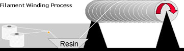
FIGURE 50: FILAMENT WINDING MOLDING
3.15 Appendix H.4
- Closed Molding
- Compression Molding ( has been discussed in section 2.5.3)
- Resin Transfer Molding( has been discussed in section 2.5.2)
- Pultrusion:
Pultrusion (fig. 9) is used for the continual manufacture of products with a constant cross section, such as rod stock or structural shapes such as beams, channels, tubing pipes, fishing rods, and in making golf clubs. This method provides parts with extremely high fibre loading tolerance meaning products have enhanced structural qualities. Similarly to previous molding techniques, continuous strand roving in addition to other materials such as mats, cloths, or surfacing, are to be fed through and impregnated into a bath of resin, which is pulled with “pul-trusion” method, through a steel die, by using a powerful tractor mechanism. At once the reinforcement joins with the steel die to become consolidated together.
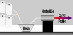
The steel die is then heated to cure the resin faster and the product shape is set, with the fibre/resin ratio being controlled.
Following on from this, types of ball-like roving called creels are located on a rack so that after this automated tensioning devices and roving guides can direct the roving into the die. Structural Composite论文代写
The molds used are from hardened steel dies that are machined and preformed to shape the resin-saturated roving constituents. Either electric heating or heated oil can be included with the steel die, although advanced pultrusion technology is changing to inject the dies directly, with the resin being introduced inside the die, instead of being saturated externally in the resin bath. It is a particular advantage that it can be adapted to a range of multiple cross-sectional shapes. Again, this method can produce a high level of strength as a result of fibre loading while costs for the workforce are less.
3.16 Appendix H.5 Structural Composite论文代写
- Vacuum Bag Molding
Another technique to improve the mechanical properties of open-mold laminates is vacuum bagging (fig. 10), which in its most basic form includes a flexible film such as PVA, nylon/mylar, or even polyethylene which covers the wet lay-up and is then totally sealed at the edges to form a vacuum.The principle of this technique is to reduce the pressure inside the vacuum bag, causing external atmospheric pressure to exert its force on the bag. The pressure removes air that is still trapped, as well as excess resin, and assists in the binding and compacting of the laminate which produces a higher percentage of reinforced fibre. Another advantage is that styrene emissions are reduced with this technique.
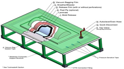
FIGURE 52: VACUUM BAG MOULDING
Vacuum bagging can be used with wet-lay laminates and pre-impregnated composite fibres during the fabrication of advanced composites.
When the process for wet lay-up bagging is used, hand lay-up can also be used to saturate the reinforcement, after which the vacuum bag has to be mounted on the mold and used to compact the laminate and for removing any voids of air. The molds are fortunately similar to the ones used in conventional open-mold processes.Another technique is to place the required material to be laid-up on the mold, following which the vacuum bag is again mounted only this time, the mold is heated or placed in an autoclave that applies both heat and external pressure, so that the force of atmospheric pressure responds. Structural Composite论文代写
This prepreg-vacuum bag-autoclave process is most frequently used to form advanced composites in aircraft and military products. A more advanced form of this method can be used by placing a release film over the laminate, followed by a bleeder ply of fibre-glass cloth, or any other kind of material used to absorb excess resin from the laminate, such as non-woven nylon or polyester cloth. This is followed by another breather ply of a non-woven fabric covering the previous layer, until the vacuum bag is able to be mounted above it all. This procedure has a similar result as the basic vacuum bag with the added pressure that results in further high fibre concentrations and forms better adhesion of the composite and reinforcement materials.
3.17 Appendix H.6
- Vacuum Infusion Processing
A variation of vacuum bagging is vacuum infusion (fig. 11) with the main difference being that the resin is introduced into the mold after the vacuum has pulled the bag down and compacted the laminate. The purpose of this method is to create lower than atmospheric pressures within the cavity of the mold.
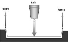
FIGURE 53: VACUUM INFUSION PROCESSING
In addition, instead of being used with a wet lay-up, this time a dry lay-up of the reinforcement and core material is used in the mold; which may include all the plies of the laminate material if required. While the mold may still get the gel coating in the traditional style, after the gel coat cures, the dry reinforcement is positioned in the mold. This can be done by hand so that the reinforcement can be positioned precisely where it is needed, then a perforated cover is stretched over the dry reinforcement. Next a coarse mesh or a “crinkle” ply is positioned with perforated tubing to distribute resin evenly over the laminate.
The vacuum bag is then put in place and sealed at the mold perimeter.
Then, between the vacuum bag and resin a tube is connected, the vacuum is applied to the laminate and the resin is pulled into the mold. After the resin has been pulled into the mold the laminate has already been compacted, restricting the likelihood for any excess resin to enter the mold. This results in a very high resin to glass ratio using vacuum infusion while the laminate has superior mechanical properties as well. Structural Composite论文代写
Vacuum infusion is suitable to mold very large structures and is considered a low volume molding process.Vacuum infusion is advantageous in production as laminates are uniform in design and consolidation, providing materials and structures that have elevated strength and at the same time are lightweight. In addition, this process uses the same conventional and inexpensive tools as open molding. Very large structures can be formed with this method. There is also a substantial reduction of emissions when compared to either open molding or wet lay-up vacuum bagging.
3.18 Appendix I
Wet samples discussion 🙁 Continue for section 4.3)
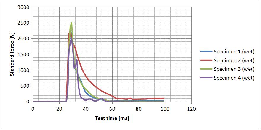
GRAPH 5: LOAD VS TIME FOR WET SAMPLES.
It can be seen that, following exposure to the impact force, the force-time curve rises up to an initiation point, which notably differs in regard to the different of treatment as 4 specimens were immersed in seawater. The force–time curve was linear up to the damage initiation point. The peak impact load values for wet and dry specimens are seen to increase until 2.171, 3.281kN, respectively. The wet samples have gained seawater approximately 10.56% of its weight. Upon reaching the peak value, the impacted specimen’s behaviour and initial damage show the capability of the specimen to absorb more energy and bear a greater load, which is markedly owing to the jute fibre effects.
From the time that the damage starts until it reaches its peak, wet samples can withstand higher loads and absorb additional energy compared to dry samples. Much of this is due to the effect that jute fibre has as a reinforcement fibre. In spite of this, as damage continues to spread past the peak load, wet samples are still able to absorb energy even until the sample eventually perforates. This visible damage then becomes clear and following this, samples soon lose their ability to bear loads, being reduced in this capability. Structural Composite论文代写
3.20 AppendixJ.2
TABLE 10: THE DATA WET SAMPLES.
For the range of different specimens (wet and dry), stability in the load-time curve indicates a greater degree of contact force, thus highlighting when impact loading in the specimen is contrasted with impact loading in other specimens. When the curve shows a small time and the results of instrumented falling weight impact testing for wet specimens, the total collapse point for initial damage is reached in roughly 98 ms. with the impact event for dry specimens being roughly 49 ms. Notably, the peak load values were found for wet and dry to be approximately 2.171, 3.281kN respectively, as can be seen in Graph5.
Furthermore, when considering the time that elapsed for damage initiation to penetration, it is shorter for wet specimens than for dry specimens;
more specifically, there is a difference in the time by roughly 3.54 ms, which indicates that dry specimens are stronger than wet specimens. With this in mind, it is therefore clear that the contact time for an impact event increases when the weight is greater.
With the above taken into account, it can be seen that there is a close link between the composite laminates stiffness and the peak impact load’s time variation. Moreover, it is clear that, with the increase of fibre reinforcement and a greater degree of composite stiffness, there is a simultaneous rise in the contract time for impact. However, the degree and extent of matric cracking could also increase alongside load rises, which subsequently results in delamination, the subsequent breakage of fibre, and finally the penetration/perforation of impacted specimens [3].
3.21 Appendix J.3 Structural Composite论文代写
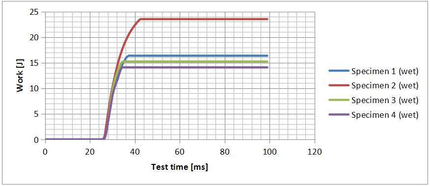
GRAPH 6: ENERGY VS TIME FOE WET SAMPLES
A number of different fracture modes are known to be included when examining and evaluating impact damage in the case of composite materials. With this in mind, Graph 6 illustrates the disparities in energy absorption. It is obvious that the jute-reinforced specimen’s total energy absorption rose until 2ed specimen, which absorbed less water (8.47%) than the other specimens, at which point a plateau was reached. For the impact test, the energy available was 23.52J, with Figure26 showing 16.38, 15.22 and 14.08 J for specimens 1,3and 4 respectively.