CENV3020 GEOTECHNICAL ENGINEERING
Assignment: Embedded retaining walls
BACKGROUND
High Speed 1 (HS1) consists of 109 km of high speed track and associated infrastructure linking the Channel Tunnel at Folkstone, Kent to the London terminus at St Pancras. Various measures were adopted to minimize the impact of HS1 in terms of noise and visual intrusion, particularly in urban areas. At Ashford, Kent, the railway runs through approximately 1.8 km of cut and cover tunnels and associated retained cuttings to minimize noise and to avoid crossing existing road and rail routes at grade. The sides of the cut-and-cover tunnels and propped retained cuttings were constructed using contiguous bored pile retaining walls, using piles varying in diameter from 900 mm to 1350 mm. Figure 1 shows a cross section through one of these walls.
It is proposed to extend the length of retained cutting, to provide additional lines running around Ashford station. At one location, a row of brick Victorian terrace houses runs parallel to the line of the cutting, with the nearest part of the houses just 12 m from the retaining wall. A contractor has proposed an outline scheme, including key aspects of the geometry required for the retained cutting (excavation depth, thickness of base slab). Figure 2 shows the dimensions, and soil conditions for, the new proposed excavation. You are asked to do some design calculations to establish the wall embedment depth, wall and prop structural loads, and wall and ground displacements.
CONSTRUCTION DETAILS 岩土工程代写
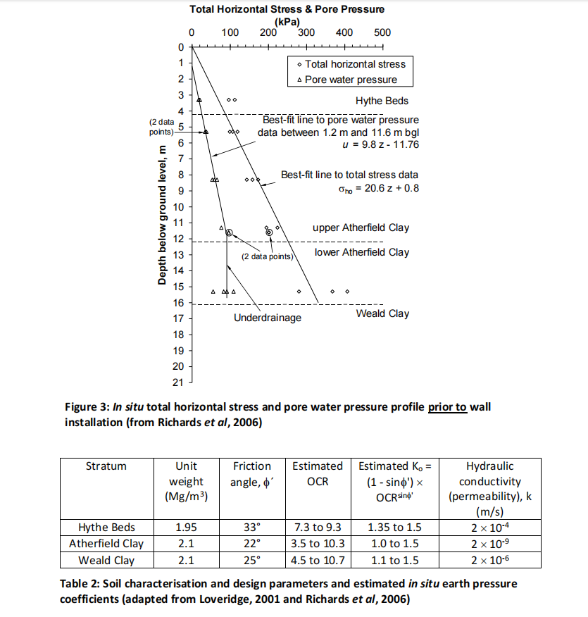
The geological succession in the Ashford area is summarised in Table 1, and geotechnical parameters and soil properties are given in Tables 2 and 3 and Figure 3.
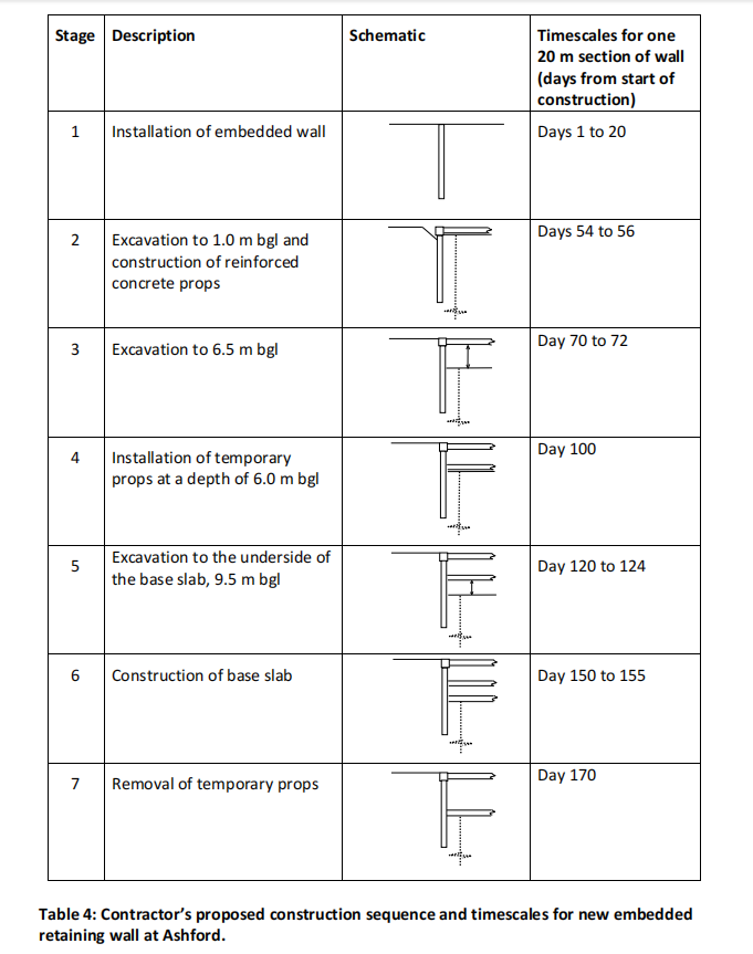
The contractor’s proposed construction sequence has seven stages, which are:
- Install the diaphragm wall (you will need to determine the design embedment depth)
- Excavate to a depth of 1.0 m bgl and install the upper, permanent props at 0.5 m bgl
- Excavate to a depth of 6.5 m bgl
- Install the temporary props at a depth of 6.0 m bgl
- Excavate to a depth of 9.5 m bgl
- Construct the base slab of 1.0 m depth
- Remove the temporary props
This construction sequence is shown schematically in Table 4.2
Due to the plant available, the contractor would prefer to build either a 1050 mm or 1300 mm thick concrete diaphragm panel wall. It is intended that the top props will be of reinforced concrete of cross section 950 mm by 950 mm and spaced at 4.5 m centres, and that the temporary props are circular hollow steel sections of 1000 mm diameter and wall thickness 25 mm. The base slab is a 1.0 m deep reinforced concrete section.
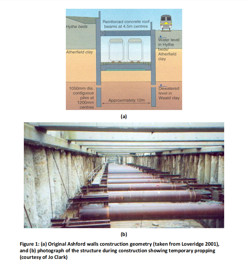
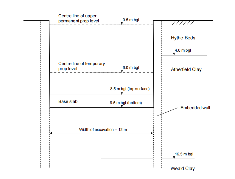
Figure 2: Wall and soil geometry for proposed new section of HS1 at Ashford (not drawn to scale).
| Stratum | Description |
| Gault Clay | Very stiff fissured clay |
| Folkstone Beds | Very dense sand |
| Sandgate Beds | Silty sand and silty clay |
| Hythe Beds | Orange brown silty or clayey fine sand with one or two poorly developed layers of sandstone (more usually interbedded Limestone (Rag) and very dense sand or weak sandstone (Hassock)) |
| Atherfield Clay | Stiff to very stiff plastic clay, frequently closely fissured. Zones containing thin silt partings were present at some locations, occurring more frequently with depth |
| Weald Clay | Stiff to very stiff clay with numerous fissures, silt partings and laminations and bands of siltstone typically 100 – 200 mm thick |
Table 1: General geological succession in the central Ashford area (from Richards et al, 2006)
| Stratum | Young’s modulus at top
surface of stratum (kPa) |
Gradient increase of Young’s
modulus with depth (kPa/m) |
| Hythe Beds | 1800 | 4860 |
| Atherfield Clay | 3600 | 3640 |
| Weald Clay | 18200 | 3200 |
Table 3: Soil stiffnesses (Young’s moduli) based on values given by Loveridge (2001).
YOUR TASK 岩土工程代写
PART 1:
Carry out Ultimate Limit State (ULS) limit equilibrium design calculations to determine the design depths of embedment and prop loads at the end of Stage 5. Follow the guidelines given in the CIRIA report C760 (Gaba et al, 2017), for Eurocode design approach DA1C2 which are [also see CIRIA guide page 190]:
i. Apply a factor of safety of 1.25 to tanf¢, i.e. tanf¢design= (tan f¢)/1.25;
ii. Take wall friction angle d = 1.0 ´ f¢;
iii. Assume that a variable unfavourable surcharge of 10 kPa applies to the ground surface at the top of the wall, and that this is increased by a partial factor of 1.3;
iv. Allow for an overdig of 10% of the excavation depth H up to a maximum of 0.5 m, where H is taken as the height retained below the lowest support level for a propped wall.
Assume fully active pressures in the soil behind the wall and fully passive pressures in front, with the design (factored) value of f¢ in each case. Make suitable assumptions regarding the pore water pressures, on the basis of the information on the in situ groundwater regime given in Figure 3 and the permeabilities in Table 2, and potential steady state flow conditions around the wall. You only need to carry out drained effective stress calculations: the quite high bulk permeability of the Weald Clay is likely to limit undrained behaviour of the clay.
PART 2: 岩土工程代写
Carry out a soil-structure interaction ULS analysis (with the factored soil strength) using the pseudo-finite element program FREW (see separate notes), to determine the required depth of embedment and the ULS bending moments and prop loads for all construction stages. To arrive at the correct wall displacements for Stage 7 at the end of the analysis, you will need to model all the construction stages in FREW. Additional parameters you will need to run this analysis are given in Table 5.
Carry out a Serviceability Limit State (SLS) analysis of the wall with the design depth of embedment (i.e. that from the ULS) and the unfactored soil strength, to calculate the SLS bending moments, prop loads and wall displacements, again modelling all construction stages. The provision for an unplanned overdig does not apply in the SLS.
PART 3: 岩土工程代写
Use your results from FREW and the method proposed in Figure 6.17 of C760 (page 170) to estimate the vertical settlements immediately behind, and 12 m from the rear of the retaining wall, along with the maximum settlement, at the end of Stage 7.
| Pre-excavation lateral earth pressure coefficient K | see Table 2 |
| Young’s modulus of soil E | see Table 3 |
| Poisson’s ratio for soil v | 0.3 |
| Wall flexural rigidity (bending stiffness) EI | Wall flexural rigidity (bending stiffness) EI see Page 1-2 for wall thickness and plan
geometry, and take E0 for concrete as 30 ´ 106 kN/m2 . Follow the guidance in C760 (see page 85) on changes to E during construction and in long-term wall service. |
| Prop stiffness k | see Page 3 for concrete and steel prop geometry, and take E0 for concrete as 30 ´
106 kN/m2 . E0 for the props should be similarly reduced to account for creep and relaxation of the concrete (i.e., you should again follow the advice on page 85 of C760). |
| Width of excavation | see Figure 2 |
Table 5. Additional parameters required for FREW analyses.
WRITE-UP
Your write-up should comprise the following sections:
i.
Detail the input parameters (factored strengths, soil/wall friction angles, earth pressure coefficients, pore water pressure conditions, design wall geometry allowing for overdig etc.) for the limit equilibrium ULS calculation, for the stage analysed (Stage 5). [12 marks]
ii.
Provide your design wall embedment depth calculation set out as per Example 9.1, 483-491, SMCA 3rdEdition [or Example 10.1 on pp. 557-563 of SMCA 2ndEdition], with soil stresses and pore water pressures at key depths set out in tabular form, clearly defined stress blocks, calculation of resulting forces and lever arms, and force/moment equilibrium calculations for Stage 5. Detail the calculation of the prop loads for the design depth of embedment. [18 marks]
iii.
Detail and justify the input assumptions and parameters for your FREW analyses, including the design wall geometries, water pressures, soil strength and stiffness, and the prop and wall stiffnesses used [12 marks]
iv. 岩土工程代写
Show graphical output from the FREW soil-structure interaction analyses for Stages 5 and 7 (one image in each case to show earth and water pressures, a second to show the bending moment, shear force and prop load, and a third to show wall displacements), for both ULS and SLS conditions at both stages. [18 marks]
v.
Show your calculations for the vertical settlements of the ground behind the wall determined described in Part 3 above (for Stage 7). Draw up a table to show the vertical settlements adjacent to and 12 m behind the wall, as well as the maximum settlement determined. [5 marks]
vi.
Draw up a table to compare the results from the limit equilibrium calculations and FREW analyses, giving maximum wall bending moment (FREW only), prop loads, wall embedment depth, and maximum horizontal wall displacement and vertical ground settlement (FREW only) for each of the analyses at Stage 5. [5 marks]
vii. 岩土工程代写
For Stage 5, provide a brief commentary on the reasons for the differences between LE ULS and FREW ULS results, and FREW ULS and FREW SLS results. [12 marks]
viii.
State which calculation results (from any stages of the analyses) you would use as the structural design loads for the wall and props, and explain why. [6 marks]
ix.
Comment on the magnitude and likely accuracy of the horizontal (wall) movements and vertical (ground) settlements obtained by calculation approaches in Part 2 and Part 3. Would any further action be required to protect the terraced houses 12 m behind the wall during construction? [6 marks]
x.
Explain how you might achieve a more efficient wall design. [6 marks]
NOTES ON ASSIGNMENT PREPARATION 岩土工程代写
- Your assumptions and calculations must be clearly set out so as to facilitate checking. You will lose marks if you do not comply with this requirement.
- Please keep your assignments concise: it should be possible to detail the calculations and explain assumptions on fewer than 15 sides. There are no marks available for repeating the question, or explaining basic soil mechanics concepts (e.g. effective stress) – so you do not need to do that.
- Neat handwritten calculations are fine – you do not have to use Word.
HELP AND SUPPORT WITH ASSIGNMENT
If you require help and advice outside the supervised sessions please get in contact:
Dr Joel Smethurst, jas@soton.ac.uk, or message me on Teams.
MARKING CRITERIA
| Marking Criteria | A (70-100%) Very good to excellent | B (60-69%) Good | C (50-59%) Fair | D (< 50%) Below MSc pass standard |
| Setting out details of and assumptions in analyses (sections i, and iii). | Input parameters set out very clearly. Assumptions made correct and very well explained and justified. | Input parameters set out competently. Assumptions made mostly correct and with sound explanation and justification. | Input parameters set out adequately. Some assumptions made correct with some limited explanation and justification. | Some input parameters not stated or unclear. Missing explanation and justification for the assumptions made. |
| Calculations (sections ii, iv, and v). | Thorough set of calculations Implemented completely correctly.
Calculations set out professionally and are clear and unambiguous. |
Calculations
implemented mostly correctly. Calculations set out professionally to be mostly clear and unambiguous. |
Calculations
implemented adequately but with some errors. Basic/adequate presentation of calculations. |
Calculations
contain significant conceptual and numerical errors or may be incomplete. Calculations not set out adequately to be always followable. |
| Analysis and interpretation of results (sections vi to x). | Exemplary analysis, understanding and interpretation of results. Some originality shown in aspects of interpretation. Written discussion is clear and concise. | Competent analysis of results, with most but not all understanding and interpretation correct. Written discussion is mostly clear and concise. | Adequate analysis of results, with some basic understanding and interpretation correct. Written discussion clear and concise only in parts. | Weak analysis and understanding of results, missing some points and with limited argument and reasoning. Poor written structure and errors in use of language making it difficult to follow. |
REFERENCES 岩土工程代写
The papers and CIRIA report below are all available on the module Blackboard.
Loveridge, F.A. (2001). Evaluation of prop loads at CTRL contract 430 Ashford Tunnels. Ground Engineering, August 2001.
Clark, J. (2006). Performance of a Propped Retaining Wall at the Channel Tunnel Rail Link, Ashford. PhD dissertation, University of Southampton.
Richards, D. J., Roscoe, H., Powrie, W. and Clark, J. (2006). Pore water pressure and horizontal stress changes measured during construction of a contiguous bored pile multi-propped retaining wall in lower Cretaceous clays. Géotechnique, 57, No. 2, 197- 205.
Clayton, C.R.I., Xu, M. and Bloodworth, A.G. (2006). Intrinsic soil behaviour and the development of earth pressure behind integral bridge abutments. Géotechnique, 56, No. 8, 561-571.
Gaba, A R, Hardy, S, Doughty, L, Powrie, W and Selemetas, D (2017). Guidance on embedded retaining wall design. Report C760, Construction Industry Research and Information Association. London: CIRIA
Key definitions for and analyses within FREW 岩土工程代写
The following notes give an overview of FREW and some suggestions about how you should attempt to model your wall problem. The notes refer periodically to the FREW version 19 manual, (which is posted on Blackboard), and you may need to make some reference to this.
1.What is FREW?
The pseudo finite-element program FREW models the wall as an elastic beam, and models the soil in front of and behind the wall as elastic blocks, for which the stiffness and boundary behaviour is controlled by predetermined stiffness matrices. Excavation of soil from in front of the wall causes the wall to come out of equilibrium – the out of balance forces then cause an initial displacement of the wall. From the wall displacements, the program can then calculate the new soil pressures acting on the wall.
The program makes a series of iterations of displacement and earth pressure until the wall either comes back into force and moment equilibrium, or the out of balance forces or wall displacements increase beyond a prescribed maximum (i.e. the wall is not deep enough and falls over). The earth pressures acting on the wall are limited by the active and passive earth pressures (which define the soil failure). By using such a calculation scheme it is possible to calculate the actual earth pressure distribution acting on the wall (rather than just the limiting pressures given by Ka and Kp), the wall displacements, the wall bending moment (from the wall stiffness and its displaced shape) and the prop load.
2.Building a model in FREW 岩土工程代写
The data input in FREW is in two categories: Global Data which affect the problem at all construction stages, and Stage Data which defines the individual construction stages. The global data are entered first. After that, you will need to input the construction stages. You will find it helpful to draw out and number the construction stages that you want to model before you start. FREW labels the horizontal soil profile before any excavation takes place Stage 0. In each construction stage it is possible to alter the size of the excavation, the presence of a prop, the pore water conditions, and the wall properties. The final construction stage should represent the final constructed condition.
3. Material Properties – basic descriptions of the key soil properties are given below.
The full definitions are given on pages 38-39 of the FREW 19.4 manual.
E0 Young’s modulus
g Unit weight of soil
K0 Pre-excavation lateral earth pressure coefficient
Ka Coefficient of active earth pressure (includes allowance for soil/wall friction)
Kp Coefficient of passive earth pressure (includes allowance for soil/wall friction)
Kac Component of active earth pressure due to cohesion component of soil strength
Kpc Component of passive earth pressure due to cohesion component of soil strength
Kr Ratio of change in horizontal effective stress to a unit change in vertical effective stress [Kr = v/(1-v)]
c0 Cohesion
y0 Reference level for cohesion and Young’s modulus (assuming that these are
specified as varying with depth)
c gradient Rate of change of cohesion with depth
E gradient Rate of change of Young’s modulus with depth
4.Nodes. 岩土工程代写
The calculation scheme requires the wall to be divided into a series of vertical discrete elements, in which the node points define the boundary between adjacent elements. The lowest node specified represents a horizontal rough rigid boundary to the problem. Nodes must be specified beyond the toe of the wall, down to a point in the soil where strains due to excavation are likely to be sufficiently small that the boundary does not interfere with wall behaviour (about half to one times the wall height should be ok). The soil depth can be initially defined in the Specification dialogue box (the soil depths are defined as reduced levels). Nodes can be created typing in the box that comes up when Node levelsis selected. (Note that FREW will also create them automatically for you – read on through this section to find out more).
The beam lengths defined by the nodes must be of approximately the same spacing, otherwise the solution will not converge properly. 岩土工程代写
Props must connect directly to a node, and excavation levels must be midway between nodes. Further details on defining wall nodes are given on pages 63-64 of the FREW 19.4 manual. The more wall nodes you specify, the more accurate the solution, and for a propped wall, around 40 nodes may be required to get a reasonable solution. FREW will also helpfully generate all the nodes for you. In the Specification dialogue box select Automatic and FREW will generate nodes automatically based on the data supplied in the dialogue box. FREW will generate the nodes as the ‘stability check’ runs.
The depth of wall embedment can be estimated by FREW using a limit equilibrium calculation: this is referred to as the ‘stability check’ (Obtained by clicking on the Stability check button, but only once much of the data below is entered). The limiting equilibrium ‘stability check’ calculation carried out by FREW for a multi-propped wall has many of the limitations (relating to e.g. statical indeterminacy) that your own limiting equilibrium hand calculation had, and generally it won’t be a good estimate of the true wall embedment depth required for stability. You can override the stability check estimate of embedment depth and enter your own: in the Specification dialogue box check the Override calculated toe level box, and enter the wall toe level that you would like the calculation to use.
5.Strut and surcharge properties. 岩土工程代写
These allow the strut and surcharge properties to be entered into FREW. The parameters to be entered are fairly self-explanatory, although additional information is given on pages 57 of the FREW 19.4 manual. You will need to enter the construction stage numbers in which the props and surcharges are present (these can be altered later on when specifying the construction stages).
6.Stage Operations – Stage 0 Initial Conditions
– You must input soil zones, water data, the analysis method and convergence control parameters for stage 0. Further construction stages can then be created. Stage 1 must define the wall depth and flexural rigidity EI. Several changes can occur at each stage so long as the effects are cumulative (i.e. you can insert the prop and excavate in one stage), but if uncertain, it is better to model more stages than too few. When you create Stage 1, the data that you have put into Stage 0 will copy into the new stage (where you can then make changes).
Wall flexural rigidity 岩土工程代写
– if you have asked FREW to automatically generate the nodes, you only need to provide a single value of flexural rigidity to the wall, and FREW will apply it to the full wall depth.
Soil zones
– if FREW is generating the wall nodes for you, you only need to tell FREW the depths at which the soil types change.
Water data
– the water pressures are assumed to be linear between specified points and hydrostatic beneath the lowest point. The program will not calculate linear seepage for you: if you want linear seepage pressures you must do this and input appropriate pressures for the base of the wall.
Analysis method 岩土工程代写
– there are two ways of representing the soil and its stiffness in FREW, one is the Mindlin method and the other is based on a stiffness matrix calculated from a finite element program (called the SAFE method). The standard stiffness matrices representing the soil blocks either side of the wall have either a uniform stiffness or a stiffness that increases linearly with depth (SAFE model only). If you have specified a number of soil layers of different stiffness the program, with the ‘generated’ option selected, will calculate an average (uniform or linearly increasing) profile from the stiffnesses that you have provided.
The soil/wall interface may be specified either as ‘fixed’ or ‘free’; this either attaches the soil to the wall, or allows the soil/wall interface to be free to slide. When wall is propped, whether the soil/wall interface is specified as fixed or free should not make too much difference to the solution obtained. The boundary representing the middle of the excavation needs to be set at half the excavation width, and the other needs to be set sufficiently remote from the wall to ensure that it has no impact on the wall behaviour. Further details on all of the Analysis method controls are given in the FREW manual.
Convergence control
– you should not need to change the convergence control parameters, and they can be left as the default values.
7.Analyse will solve the problem. 岩土工程代写
The calculation view tabulates the calculated wall displacements, earth pressures, bending moments and shear force. If your wall is not stable, and falls over, there will be no results for the final stage, and an error message about wall displacements in the results data. The results data also gives the maximum values of wall bending moment and shear force for each construction stage. This can be copied and pasted into Excel, to create plots of bending moment etc.
8.Graphical Output allows you to view the results in graphical form.
The Graphics menu allows what is being plotted to be adjusted. The output graphic can be exported into Word by saving as a Windows Metafile (using Save Image).

更多代写:cs加拿大网课代考价格 gre考试作弊 英国经济学网课代上 开题论文代写 经济作业Econ&Business学习 EE课业代做