280823 – Mooring Systems (2018-2019)
Mooring Systems代写 There a total of 4 exercises. In order to assess this coursework, at least 2 out of the 4 exercises have to be com- pleted
Assignment 2 / Finite Element Analysis
MÀSTER UNIVERSITARI EN ENGINYERIA NAVAL I OCEÀNICA MÁSTER UNIVERSITARIO EN INGENIERÍA NAVAL I OCEÁNICA MASTER’S DEGREE IN NAVAL AND OCEANIC ENGINEERING
Rafael Pacheco rafael.pacheco@upc.edu
03-01-2019
Contents Mooring Systems代写
- Instructions 4
- Guidelinesand Format 4
- Listof Students 5
- Background6
- PotentialFlow 6
- Model 6
- Post-processingOptions 8
- FEM 8
- Linear 8
- Non-Linear 9
- Exercises 11
- Exercise1 11
- Exercise2 12
- Exercise3 13
- Exercise4 14
- PotentialFlow 6
List of Figures
4.1Meshof the flow around the frame mooring of the Fixed Note that latitude is y and longitudeis x…………………………………………………………………………. 6
4.2Potentialflow field of the flow around the frame mooring of the Fixed Note that latitude is y and longitude is x ………………………………………………………7
4.3Velocityvector field of the flow around the frame mooring of the Fixed Note that latitude is y and longitude is x v…………………………………………………..7Mooring Systems代写
4.4Pressure distribution of the no obstacle route. Note that latitude is y and longitudeis x……………………………………………………………………………8
4.5Linear1D elasticity simulation of a frame structure……………….. 9
1 Instructions Mooring Systems代写
There a total of 4 exercises. In order to assess this coursework, at least 2 out of the 4 exercises have to be com- pleted – understanding completeness as the capability which the student possesses in order to undertake a problem, independently whether the results of it are correct or not – and the weighted value of each one of these 4 is:
| Exercise | Weight (%) |
| 1 | 25 |
| 2 | 25 |
| 3 | 25 |
| 4 | 25 |
Table 1.1: Weighting of each exercise.Mooring Systems代写
Further decomposition may be given in the problem statement.
2 Guidelines and Format Mooring Systems代写
The format must be precise and clear. Avoiding excessive decorative ornaments when possible. The message has to be precise and concise.
The development has to be clear and cannot – in any circumstance – lack of continuity or neglect common assump- tions.
In order to submit the coursework, do take special consideration that any page is not missing numbering, author identification – namely name and surname – and the name of the course subject with its identifier (280823 – Mooring Systems (2018-2019)).Mooring Systems代写
As a suggestion, do consider to submit this coursework in typewritting format. However, it is not a mandatory re- quirement, so the student is free to submit a handwritting copy.
The submission will be by e-mail and/or via the Virtual Campus (ATENEA) on the 18-01-2018 at 23:59 h. There will be an extra 2h slot – corresponding to 01:59 am – to submit the coursework by e-mail to rafael.pacheco@upc.edu if any technicality was to happen, obviously, this has to be addressed in the e-mail and justified. Note, always, using the rules detailed in the first lecture.
By technicality,
it should be refer as an event of major nature which does not allow the student to submit the course- work on the right deadline. Repetition, abuse of this procedure or implausible justification will be carefully examined and the corrector will estimate whether the coursework is collected or not. The resolution is not open to debate.Mooring Systems代写
In the case the student has not delivered on the announced deadline and the extra 2h exemption is not applicable, the student is still eligible to submit the coursework. However, the coursework final mark will be reduced by the following rule:
n(days) = .(1 − days ) · n0.
Where . · . is the so-called Macaulay brackets notation. Meaning that after 5 days a zero mark will be awarded.
Any external references or computational tool has to be mentioned and listed – it is very important to cite the refer- ences, not only list them – and if it is self-developed the respective code has to be annexed.Mooring Systems代写
Any result obtain by eye will be awarded a zero mark since it could be just copied. Be rigorous and use any numerical technique of your choice.
3 List of Students
| SURNAME, NAME | Group |
| BERNIERI, LORENZO | ? |
| BOLDÚ SARDANS, JAUME | ? |
| CASTELLS ROSET, JORDI | ? |
| CHAUHAN, ABHISHEK KIRITKUMAR | ? |
| DING, YANG | ? |
| FERNÁNDEZ BARRANCO, VALENTÍN | ? |
| LÓPEZ SÁNCHEZ, ÓSCAR | ? |
| LUO, LUYAOMooring Systems代写 | ? |
| MARRE ROSALES, GIOVANNI | ? |
| MINGOT VALENCIA, CARLOS | ? |
| NERGAARD, ANDREAS WAAGO | – |
| PASCUAL SOLDEVILLA, ERIC | ? |
| PEIRÓ VISPE, SERGI | ? |
| REINA JEREZ, KEVIN | ? |
| RIVERA MORCILLO, SERGI | ? |
| TURON PUJOL, FRANCESC | ? |
| VALLDOSERA DOMINGO, ORIOL | ? |
| VIDAL VILA, ROC | ? |
| ZHANG, MEIMAN | ? |
Table 3.1: Student list course 2018-2019 in alphabetical order.
Note the parameters assigned are generated based on the some significant information of each individual, meaning that there are no two identical solutions. Each group has a solution of its own, notwithstanding each problemmaintains the uniqueness for procedural resolution. I.e., the level of assessment is unique disregard the group .
Any group who has completed and submitted the minimal number of exercises for this coursework, is eligible toexercise its right to express any discordance with the level of assessment for its specific case. If this prove to be right,a compensation will be awarded.Mooring Systems代写
This right shall be exercised by completing an exhaustive development of why the group believes the level is higher than the average expected, note that for a lower level of assessment, this right becomes void. Reflect in a concise and clear essay the different reasons of such statement and submitted it by e-mail. The corrector reserves the right to propose an appointment to further discuss if the group has proven to be right based on the essay presented.
4 BackgroundMooring Systems代写
4.1 Potential Flow
Execute the script LAPLACE.m to simulate the flow around a fixed platform made of truss elements and moored to the seabed. Assume perfect bounding between the seabed and the platform.
Execute the Octree.m to create an octree and use Find_Position.m to find the pressure at a given point (x, y ).Mooring Systems代写
4.1.1 Model
- FixedPlatform:
Note that from a structural point of view, the Fixed Platform domain of interested will only correspond to its underwater frame structure. Also any boundary layer around the frame will be neglected in the macroscopic scale. The velocity magnitude can be considered relatively slow to use potential flow theory.Mooring Systems代写
This model corresponds to a casetype equal to:
casetype = 1;
Mesh
longitude
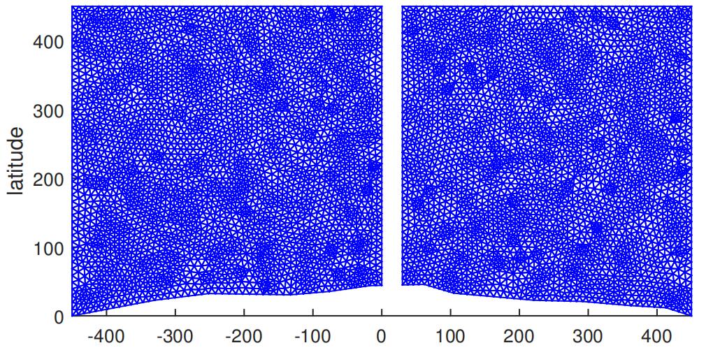
Figure 4.1: Mesh of the flow around the frame mooring of the Fixed Platform. Note that latitude is y and longitude is x .
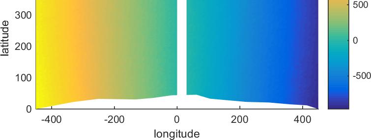
Figure 4.2: Potential flow field of the flow around the frame mooring of the Fixed Platform. Note that latitude is y and longitude is x .
r)
longitude
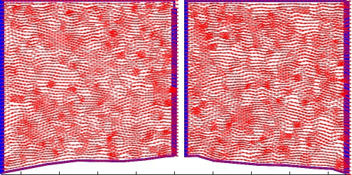
Figure 4.3: Velocity vector field of the flow around the frame mooring of the Fixed Platform. Note that latitude is y and longitude is x .
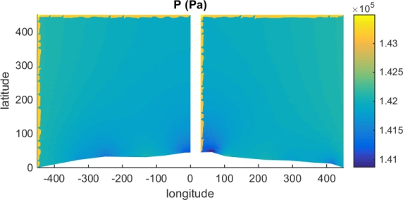
Figure 4.4: Pressure distribution of the no obstacle route. Note that latitude is y and longitude is x .
Note that this mesh contains 12752 elements (nel ms = 12752) and 6560 nodes (nnod e = 6560).
4.1.2 Post-processing OptionsMooring Systems代写
Setting in the code section:
%% Enabling P o s t P r o c e s s Options
PostProcess . Mesh= 0; % Time−Consuming Procedure PostProcess . P o t e n t i a l = 0; % Time−Consuming Procedure PostProcess . Gradient = 1; % Needed
PostProcess . V el oci ty S cal ed = 1; % Needed
PostProcess . Pressure = 0; % Time−Consuming Procedure
The importance of this section is that enabling (= 1) the options Potential and Pressure will increase significantly the time of the analysis and to a lesser extent, but not negligible, the Mesh option.Mooring Systems代写
The Gradient is needed to compute ∇Φ and Velocity Scaled gives simply the velocity direction of the gradient nor- malised.
4.2 FEMMooring Systems代写
Geometric Analysis
4.2.1 Linear
The default model is the simple frame Fixed Platform again. This model is loaded by setting in the FEM2D.m :
%% Model
model= 2; Mooring Systems代写
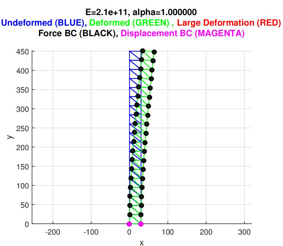
Figure 4.5: Linear 1D elasticity simulation of a frame structure.
4.2.2 Non-Linear
In order to execute the code, the document Input.m has to be launched. This analysis tool has been developed using MATLAB classes, however the group will only need to modify the sections of the code in Input.m and Core.m.Mooring Systems代写
The Non-Linear Geometric analysis allows to run static analysis and pseudo-dynamic analysis. The term pseudo- analysis refers in this context to the introduction of a pseudo-time load. The analysis can be performed in 3D-space.
The Non-Linear Geometric analysis matrices to be completed by the student are:
- MassMatrix:
M elm = ρ AL0 Σ2I3 −I3Σ (4.1)Mooring Systems代写
- Linear StiffnessMatrix:
6 −I3 2I3
K elm = E A Σ I3 −I3Σ (4.2)
- Non-LinearGeometric Displacement vector (cosinus product):
d = d x −d x (4.3)
where d x is the global axis non-linear geometric displacement due to the Total Lagrangian formulation which introduced an angle dependence respect an initial configuration.
-
Non-Linear Geometric StiffnessMatrix:
K elm = E A εGL (d · d T ) (4.4)
N L 30Mooring Systems代写
where the Green-Lagrangian deformation norm is defined by:
L2 − L2εGL :=02L2(4.5)
- ExternalForce (Hydrostatic Force)
F elm = 1 AL(ρ − ρambient) Σg Σ (4.6)
- Internal Force (Non-LinearGeometric):
ext 2 gF elm = E A εGL d (4.7)int L0Mooring Systems代写
The physical parameters above are members of the variable ’elm’ which has a data type STRUC. The notation for In is equivalent to:
where δi j is the Kronecker delta.
In := δi j , i , j = 1, . . . , n (4.8)
5 ExercisesMooring Systems代写
5.1 Exercise 1
Linear 1D Elasticity FEM.
- Copythe geometry and boundary conditions for model 2 into model Modify the material parameters to:
E = A = ρ = 1, b = [0, 0] . Modify the Force per length parameters P = 5e − 6. For a fixed nx = 2 and ny = 20, increase H from 1 to 16 m. L = 1. Comment and discuss the results.
- Copythe geometry and boundary conditions for model 2 into model Modify the material parameters to:
E = A = ρ = 1, b = [0, 0] . Modify the Force per length parameters P = 5e − 6. For a fixed nx = 2 and ny = 20, increase L from 1 to 16 m. H = 16. Comment and discuss the results.Mooring Systems代写
-
Copythe geometry and boundary conditions for model 2 into model Modify the material parameters to:
E = A = ρ = 1, b = [0, 0] . Modify the Force per length parameters P = 5e − 6. For a fixed H = 20 and nx = 2, increase ny from 2 to 20. L = 1. Comment and discuss the results.
- Formodel 2, suppose you have a perforation drill passing through the line x = 15 without loads the vertical displacement can be neglected, however the maximum displacement allowed would be no more thanL/2, where L = 1.5. Dimension the area of the frame members to satisfy that condition.
- Create your own frame structure able to endure a load P (y ) = 5e3 y applied on each joint. (Hint: you can make useof pdetool –unstructured mesh – or similar tool – structured mesh – to create the external shape of your frame structure and mesh it in triangles. Then use the code inside input_geo.m that transforms the connectivity matrix ’Ttri’ into a bar connectivity matrix ’T’)
5.2 Exercise 2Mooring Systems代写
Non-Linear Geometric 1D Elasticity FEM.
- Introducethe Mass Matrix, Linear Stiffness Matrix, Non-Linear Geometric Stiffness Matrix, External Force Vec- tor and Internal Force Vector inside m and core.m.
- Using the default values found in the code, launch the analysis for an incremental of pseudo-time dt = 2, dt= 0.1 and dt = 0.01. The time scheme has to be ’None’. Comment on the results obtained.
- Using the default values found in the code, launch the analysis for an incremental of pseudo-time dt = 2, dt= 0.1 and dt = 0.01. The time scheme has to be ’Newmark’. Comment on the results obtained.
- Using the default values found in the code, perform a convergence analysis in terms of the incremental of pseudo-timedt = 2. The time scheme has to be ’Newmark’.
(Hint: a convergence analysis is one where you normally reduce to a half the mesh grid size each time until the results converge up to a certain tolerance τ, in here the mesh grid size is the increment of time.)Mooring Systems代写
- Comparethe results between the question 1 and 2 in terms of accuracy, computational time and physical/- constitutive
5.3 Exercise 3Mooring Systems代写
Non-Linear Geometric 1D Elasticity FEM. Theory.
- Providedthe definition of the Mass Matrix
M elm := ∫ ρN T · N j d Ω (5.1)Ω
Show that Equation (5.1) is equivalent to Equation (4.1) for linear bar 1D in 3D space.
(Hint: the mass is equivalent to all 3 dimensions, if the domain was a 2D domain the Mass Matrix element in Equation (4.1) would change I3 for I2 and analogously for 1D. Meaning that you only need to derive it in 1D and extent it to nD by multiplying each cell in the [2 × 2] 1D-Mass Matrix by In )Mooring Systems代写
- During the course the definition of weak and strong form have been briefly explained in a simple Could youdescribe both approaches and thus why are they different. Why we use the weak approach in FEM.
- During course two procedures have been used to obtain the weak form of a physical problem, namely the variationalform (linear elasticity) and principle of virtual work (non-linear elasticity).
Given the strong form of 1D elasticity:
Ω := (0, l )
∇(AE ∇u) + b = 0 ∀x ∈ Ω
σ = E : ε = 0 x = 0
u = 0 x = l
(5.2)
Where : is the double cross product that in 1D is equivalent to dot product. Show that the weak form is equiv- alent to:
l ∫l 0 ∇v · AE ∇ud x = v bd x , { v v (l ) 0} (5.3)
Use any of the two explained methods to obtain the weak in Equation (5.3). If you show both, variational derivation and the principle of virtual work, the group final score for exercise 3 shall be 100% if the derivation is understandable and somehow correct.Mooring Systems代写
5.4 Exercise 4
FEM Coupling. Theory.
Imagine you would like to couple two different physical natures such as a fluid problem together with a structural problem. This is commonly referred as a fluid-structure interaction coupling (FSI). There is also the possibility to couple two structural problems and it is also known as solid-solid interaction.
There are two common approaches, one option is to use monolithic system of equations – no iterations– or the other option would be to use domain decomposition – mostly iterative method – to solve smaller systems of equations. Within the domain decomposition, one can extract certain level of parallelism.
For domain decomposition, there are different techniques such as sequential schemes (where one analysis controls and waits for the other to calculate in order to update its inputs) or staggered schemes where both problems execute in parallel and perform several iterations where they exchange information (fluxes) useful to minimise the residual between internal and external forces.Mooring Systems代写
- Launchthe Potential Flow code and explain the advantages of using a octree structure in terms of the mesh element number and computational
2.Imagine you want to substitute, in exercise 1, the external force introduced as a function of the depth multi- pliedby a force per unit of length by using a FSI Explain how could this be performed.
3.It is well known that a beam fixed on both extrema presents a deflection similar to one of a cable. Could you discussif using a beam element model is sufficient in some cases to simulate a
4.Imagine you want to take into accoun Mooring Systems代写
t the dynamic pressure from the current in your mooring line composed ofa cable fixed on both To do so, you would like to to introduce a FSI coupling. Comment on how would you do this.
5.Imagine you want to take into account the interaction between two structures (cable and frame structures). What type of coupling would you introduce and how would you transfer the information between the two different (Hint: Remember that prescribed displacement or Dirichlet boundary induce a reactionforce that can be computed once all the displacements are known. Fluxes are equivalent to forces in a solid-solid interaction).Mooring Systems代写
6.Combiningthe hypothetical scenarios above, could you perform an accurate analysis of an offshore mooring system compound by cables (catenary/taunts) and frames?Could you think a better solution for the solid-solid interaction problem (staggered scheme) between the cablemooring line and the frame mooring provided a staggered scheme is generally better than a sequential?
更多其他:C++代写 考试助攻 计算机代写 report代写 project代写 java代写 algorithm代写 代写CS 代码代写 function代写 作业代写 course代写 Data Analysis代写 app代写 Exercise代写