ELEC3400 Take-Home Exam
电气与电子工程代写 You just got hired in a Biomedical Instrumentation company that is leading a fast-tracked project to combat COVID-19.
You need to submit the solutions before 4th of April 2020 at 13:00. Unless advised in the Course Profile, assessment items received after the due date will receive a zero mark unless you have been approved to submit the assessment item after the due date.
All questions should be answered and full working should be shown for all questions.
Question 1 (35 marks) 电气与电子工程代写
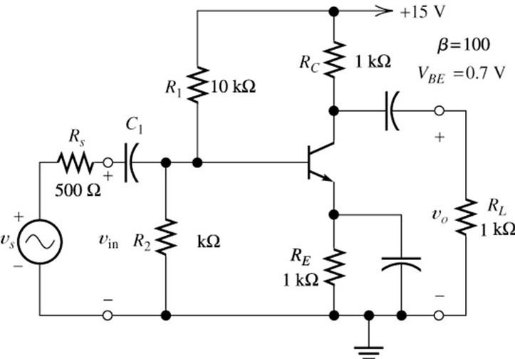
For the amplifier shown in Figure 1,
(a)What is the name of thisamplifier configuration? (1 mark)
(b)Draw the dc circuit and calculate the collector current and VCE at Q-point. (10marks)
(c)Determine the operating region of the transistor andexplain (2 marks)
(d)Draw the small signal circuitand calculate: (4 marks) 电气与电子工程代写
i.open loopgain (Avo), (3 marks)
ii.inputimpedance (Zin) (2 marks)
iii.outputimpedance (Zout) (3 marks)
iv.loaded voltage gain(𝐴𝑉L) (4 marks)
v.loaded current gain(𝐴𝑖l) (4 marks)
vi.powergain (G) (2 marks)

Figure 1
Question 2 (25 marks) 电气与电子工程代写
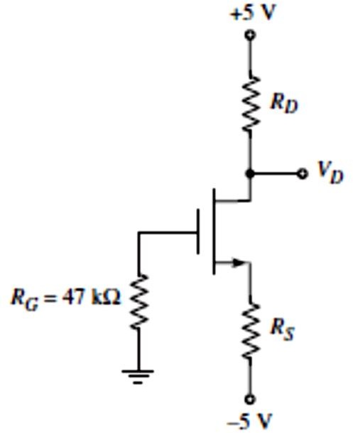
For the circuit shown in Figure 2, the MOSFET parameters are K= 0.25 mA/V2 and Vto = 1.4 V.
(a)Assume the MOSFET is in the saturation region, calculate RD, Rs and VGS where IDQand VD are given as 0.5 mA and 1 V respectively. (7 marks)
(b)Check the assumption, is your assumption correct? You need to provide allcalculation steps. (3 marks)

(c)Plot output characteristic curve, draw the load-line andplot Q-point. (3 marks)
(d)Choose standard resistor values that are closest to the ideal designed values for Rs and RD and calculate VDS, VGS and ID at Q-point. (8 marks)
(e)Ifthe standard resistor Rs has ± 10% tolerances, determine the maximum and minimum values of IDQ. (4 marks)

Figure 2
Question 3 (40 marks) 电气与电子工程代写
You just got hired in a Biomedical Instrumentation company that is leading a fast-tracked project to combat COVID-19.
One of the specifications of the device is to measure the temperature from 20 – 50°C.
- Youhave identified a sensor module which provides a measurement as a linear voltage between 0 and 2.5mV. It has an output impedance of 8.4 kΩ.
- You want to amplify this signalsuch that you get the best resolution out of a 12-bit analogue to digital converter (ADC), which has a reference range of 0-10V. It has an input impedance of 1.8 kΩ.
- Theamplifier is to be built out of some BJT amplifier modules that you have available:
- Zin=160 kΩ, Zout=12 Ω, Avo=0.998 (Common CollectorAmp)
- Zin=3.8 kΩ, Zout=18.2 kΩ, Avo=3.12 (Common EmitterAmp)
(a)What is the overall gain required to achievethis amplification? (1 mark)
(b)Draw equivalent amplifier models for both of the listedBJT (4 marks)
(c)Whatis the minimum number of stages you need to meet your requirements? Draw this cascaded circuit model as a block diagram, showing the sensor and the ADC load. Calculate input and output impedances and the voltage gain and study the loading effect per each design step. Show full working including block diagrams and calculations.(20 marks)
(d)Forthe cascaded model above, indicate the gain of each stage and calculate the overall gain. Does your calculated gain satisfy the gain requirement for the device? (2 marks) 电气与电子工程代写
(e)How does your calculated gain affect the ADC? One possible solution to negate the effectof the calculated gain on ADC is to place a series resistor between the final stage of your multistage amplifier and the ADC input. Calculate the value of the series resistor. (6 marks)
(f)Simplifythis multistage amplifier module to show the overall Zin, Zout and Avo and draw its equivalent voltage-amplifier (3 marks)
(g)Finally, convert the voltage-amplifier module achieved in part (f) to its equivalent current-amplifier module and draw the currentamplifier (4 marks)
End of the exam

更多代写:北美计算机作业代写 Planning代考 Proofreading英国代写 Science Essay代写 Reflection paper 代写 留学cs代考
