CSE 468/568: Robotic Algorithms
Robotic Algorithms代写 he objective of this assignment is to autonomously plan and execute a path for a robot in the Stage simulator
A* Planning and Execution
VERSION 1
PA2, Fall 2019
DEADLINE: October 17, 2019 11:59 pm
INSTRUCTOR: Vivek Thangavelu
WRITTEN BY: Vivek Thangavelu and Zijian An
I.Objective Robotic Algorithms代写
The objective of this assignment is to autonomously plan and execute a path for a robot in the Stage simulator from a start location to a goal location, given a map. The global plan is given by A* and the local planning is done using a modified Vector Field Histogram (VFH) (Refer Section IV.6).
II. Description
1. Supplied Files
The ros_pa2.tar.gz compressed file contains three files:
- txt– The map of the simulator world described as a 1D array with 0s and 1s
- pgm– Bitmap image used to describe the obstacles and free space for the stage simulator
- world– Configuration file for the stage simulator that defines the robot and its environment (using the playground.pgm file)Robotic Algorithms代写
2. Deliverables
- Youwill write node(s) to implement the VFH and A* The default start location is (-8.0, -2.0) and the default goal location is (4.5, 9.0) . The goal should be defined as two ROS global parameters, ‘goalx’ and ‘goaly’, both of which should be of type double. This allows us to set a new goal position through the ROS parameters before running the nodes, and the robot will then plan a path to the new goal. Please go through the tutorial on ROS Parameters
- Thefinal package should contain a launch file that should bring up the stage simulator (using the given world file) and your nodes.
III. Initial Setup
- Downloadand extract the supplied files for PA2
(SHA256: 7a7c43abe7842faa43873568b0979d4c0b6f08b86c1bcef7768168537e06abe6)
- Createa new package called ros_pa2
cd~/catkin_ws/src

catkin_create_pkg ros_pa2 std_msgs geometry_msgs rospy roscpp

cd ~/catkin_ws

catkin_make source ~/.bashrc
- Place the world files (playground.pgm and playground.world) into an appropriate subfolder withinros_pa2. (Similar to the ros_pa1 package)Robotic Algorithms代写
- Createa launch file called palaunch in ~/catkin_ws/src/ros_pa2 to run the stagesimulator using the given world file. You can copy the launch file from PA1 and edit it accordingly.
IV. Concepts Robotic Algorithms代写
1. Simulator
Stage is a 2(.5)D robotics standalone simulator. It provides a virtual world populated by mobile robots and sensors, along with various objects for the robots to sense and manipulate. The stageros node wraps the Stage 2-D multi-robot simulator, via libstage for ROS. Stage simulates a world as defined in the playground.world file, present inside the world sub-folder. This file tells stage everything about the world, from obstacles (usually represented via a bitmap to be used as a kind of background), to robots and other objects.Robotic Algorithms代写
You can change the view in the simulator and move the robot in stageros. You can addsome basic visualizations such as the laser scanner range data or the robot footprints for debugging from the View menu in stageros.
2. Robot Motion
The robot in stageros simulates a 2 wheeled differential drive robot that drives over a smoothground plane. In order to move the robot in the simulator, we need to send velocity commands tothe robot. This is done by publishing command geometry_msgs/Twist messages to the topic/cmd_vel. The robot can only respond to linear velocities in the x axis and angular velocities in thez axis. So, to move forward, publish Twist messages with non-zero linear.x velocities and to turn, publish Twist messages with non-zero angular.z values.
A simple behaviour to move your robot without using the more complicated differential model isto always have only an angular or linear velocity at a specific time to turn or move forward, respectively.Robotic Algorithms代写
To know the pose of the robot, you can subscribe to /base_pose_ground_truth of typenav_msgs/Odometry and retrieve the position and orientation from the pose member variable. Orientations are expressed as quaternions in ROS. Please refer to section VII.3 for conversion between quaternion and euler angles.
3. Sensor
In order to make sense of its environment, the robot needs to get data from its sensors. The robot is equipped with a planar laser range-finder that gives information about obstacles around the robot. The sensor has 361 lines of lasers allowing the robot to perceive 180 degrees of the worldaround it at a maximum range of 3m. In your stageros simulator, you can view the robot sensing range by clicking on View -> Data or pressing the key ‘D’.
The sensor data is published to a topic /base_scan which is of type sensor_msgs/LaserScan. Use the ranges[i] member variable to get the range information of a particular laser line i. If there isan obstacle between range_min and range_max, range will be the distance of the sensedobstacle from the sensor. If an obstacle is outside its range values, the range will be equal torange_max. Move the robot around by clicking and dragging it in the simulator and visualize theoutput of the sensor in rviz to understand how the sensor works. Subscribe to the topic and readthe messages to get the values of range_max, range_min, each range data, etc.Robotic Algorithms代写
4. Map
Global planners require a map for operation. The map of the robot workspace in the simulator isgiven as an occupancy grid, a grid representation with 1s and 0s, with 1 indicating an obstacle inthat cell and 0 representing an empty cell. The map has 20 rows and 18 columns. The map isdescribed as a 1D array with 0s and 1s in map.txt. You should include this into your program asthe map. You can simply paste the array into your code and read it appropriately as a 2D matrix with dimensions of (20, 18).
5. Global planner (A* Planning):
A* is an informed search technique used to search for a path from a start location to a goal location in a map. The total cost of a node n is given by:
f(n) = g(n) + ε.h(n)
where g(n) is the exact cost of the path from the start node to the node n and h(n) is the heuristic function which estimates a cost from node n to the goal node.Robotic Algorithms代写
Figure 1 depicts the movement cost from a node n (shown in green) in the occupancy grid to its 8 neighbours (shown in blue). The movement costs to the non-diagonal neighbours is 1 and the movement costs to the diagonal neighbours is √2 = 1.4. Using these movement costs and keepingtrack of the path taken, the exact cost of the path from the start to any node n in the occupancygrid can be calculated by the sum of the movement costs along the path taken.
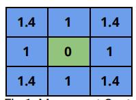
Fig.1: Movement Cost
Given the current node and the goal node, you can use the Euclidean distance (L2 Norm) between them as the heuristic cost.
The A* algorithm essentials outputs a global path from the start node to the goal node. The globalpath essentially contains a list of nodes/checkpoints, such that when the robot moves to each oneof them in succession it will eventually reach the final goal location. ε is the coefficient of theheuristic function, used to scale the heuristic cost. You can start with ε=1, and tune only ifrequired, based on the paths returned by your A* algorithm.
You may refer to this video for a walkthrough of the A* algorithm.
6. Local planner/Obstacle Avoidance (VFH): Robotic Algorithms代写
The precision in the map may not capture all the minute details in the simulator. Blindly following the path outputted by the global planner may lead to your robot crashing into obstacles. The local planner utilizes sensor data for obstacle avoidance to travel to each checkpoint in the global path, and eventually reach the final goal location.
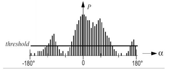
Fig.2 Polar Histogram
You will need to implement Vector Field Histogram (VFH) for obstacle avoidance. To make thingssimple, we skip the first step of deriving a local map around the robot based on recent sensorreadings. Instead, the sensor data from topic /base_scan is directly used to construct the polar histogram. The steps involved in the modified VFH are as follows:
- Convertthe sensor data into a polar histogram by grouping the sensor data at differentangles into bins of specific size (a bin size of 5 might be a good start), similar to the polar histogram shown in 2.Robotic Algorithms代写
a.xaxis – angle α at which the obstacle is found
b.yaxis – count of obstacles in that bin
c.choosea reasonable threshold to filter out noisy sensor data (i.e a bin with a count less than the threshold may be treated as a bin with no obstacles)
2.Allopenings large enough for the robot to pass are found (this can be approximated based on your interactions with the simulator, considering the sensor range and the robot size specified in the world file)Robotic Algorithms代写
3.Computecost function G for all openings:
G = a * target_direction + b * current_direction + c * previous_direction
where target_direction is the difference between the chosen direction and the goal direction, current_direction is the difference between the chosen direction and the current heading direction, and previous_direction is the difference between the previously selected direction and the chosen direction. The coefficients a, b and c tune the behavior of the robot.Robotic Algorithms代写
- Openingwith the lowest cost function G is chosen
NOTE: You will need to figure out the values of the coefficients and histogram bin sizes that worksbest for your specific implementation. You may need to add some tweaks to the VFH algorithm forobstacle avoidance, as you did in PA1 for BUG2 with interim behaviours. This might be requiredbecause in both PA1 and PA2, we do not explicitly model the dynamics of the robot system.
7. Translation between Simulator and Map Robotic Algorithms代写
Given a position in the simulator, you will need to devise a method to find the position (grid index) in the map. This would be required for translating the start and goal locations from the continuous, simulator world to the discrete map representation.
Similarly, a position (grid index) in the map needs to be translated to a position in the simulatorworld. This would be required for translating the nodes/checkpoints in the global path specified inthe map representation, to the simulator world coordinates.
These calculations can be derived by knowing the limits of the simulator world and the map.
8. Coordinate Frames
In this robot system, there are 4 coordinate frames of reference. For this PA, we only care about the following aspects of the various frames of reference:
- Theabsolute coordinate frame of reference is named odom e. the root of the tree data structure that represents the various frames.
- Therobot’s frame of reference is the base_link frameRobotic Algorithms代写
- Therobot pose is expressed in the odom frame
- Thegoal position is expressed in the odom frame
You do not have to worry about the other frames that exist in the system as all the poseinformation is expressed in the same frame (odom) and the distances of the obstacles are measured from the robot’s frame.
V. Implementation Tips Robotic Algorithms代写
Implementation in robotics can be a daunting task with multiple sub-objectives in robot control, namely local planning and global planning. It is always a good idea to list out the sub-objectives for your task and modularize your code accordingly. Below is a set of sub-objectives that might help you organize your work for this PA. You do not have to follow this strictly and is presented here purely as an example.
- Readthe txt as a 2D array
- Writemodules to translate between the simulator and the map
- Basedon the map, implement A* algorithm to extract a global path between the start and goal nodes
- Convertsensor data into a polar histogram of a specific bin sizeRobotic Algorithms代写
- Implementthe modified VFH algorithm
- Giventhe global path as a list of checkpoint positions in the simulator world, move the robot using the VFH algorithm towards the next closest checkpoint
- Repeatthe above step for every checkpoint until you reach the final goal location
- Readthe goal location in your node as ROS parameters
VI. Submission Instructions Robotic Algorithms代写
We will be using autolab in this course to submit your programming assignments. In the autolabcourse page, select pa2 and then submit a tarball of your entire ros_pa2 folder. From the fileviewer, you can right click ros_pa2 and click compress to get a tarball of the entire folder. Thedeadline for submission is October 17, 2019 11:59 pm. The deadline will be strictly enforced soplease submit once much earlier to test out the system. You are allowed to make multiplesubmissions. We will use the final submission version to grade your programming assignment.
Late Submission Policy
You may choose to submit the assignment late by a maximum of 2 days. Each day you lose 25% ofthe full grade. Hence, by submitting one day late, you lose 25% and by day 2, you lose 50%. The deadline for each extra day is 11:59 pm.
VII. FAQ
1. What will I learn from this PA?
At the end of the PA2, you will have learned:
a.Howto make your own ROS package and use ROS parameters
b.How to perform an informed search technique to extract optimal/close-to-optimal global pathsfor a robot, given a map
c.Howto implement a local planner for the robot to execute the global path
2. How to read map.txt as a 2D array?
a.Youcan copy the array values from txt and paste it into your python script/c++ source file
b.Youcan use the grid size mentioned in Section 4 to convert the 1d representation into a2d array (For python, you may use numpy to restructure the 1d array into a 2d array)Robotic Algorithms代写
3. How to transform from quaternion to euler?
ROS uses quaternions to track and apply rotations. A quaternion has 4 components (x,y,z,w). Aquaternion is an another way to express a 3d rotation in space. You can convert a 3d orientationfrom quaternion to euler angles and vice versa. You may refer to the following links for example code:
For Python: https://answers.ros.org/question/69754/quaternion-transformations-in-python/
For C++: https://gist.github.com/marcoarruda/f931232fe3490b7fa20dbb38da1195ac
4. How to import/include a message module?
Every message is defined inside a package. So you must first know the name of the package and the message type. For example, /cmd_vel is of type geometry_msgs/Twist. geometry_msgs is the name of the package and Twist is the type of message.
To import in Python:
from <pkg_name>.msg import <msg_type>
To include in C++:
#include “<pkg_name>/<msg_type>.h”
5. rosrun does not run my node
Python:
a.Makesure your python script is in the scripts folder of your ROS package
b.Makesure you have given executable privileges to your python script:
chmod +x <script_name>.py
c.Addthe python header to your script:
#!/usr/bin/env python
C++:
a.Makethe necessary changes to the txt file inside your package folder Robotic Algorithms代写
b.Makesure you ran catkin_make and sourced your bashrc file:
catkin_make

source ~/.bashrc
VIII.References:
- ROS Package:http://wiki.ros.org/ROS/Tutorials/CreatingPackage
- ROS Parameter:http://wiki.ros.org/Parameter%20Server
- Stage1.1 Manual: https://codedocs.xyz/CodeFinder2/Stage/md_README.html
- stageros Wiki:http://wiki.ros.org/stage_ros
- A*Algorithm Walkthrough: https://youtube.com/watch?v=-L-WgKMFuhE
- Histogram: https://en.wikipedia.org/wiki/Histogram
- Autolab: https://autograder.cse.buffalo.edu/courses/CSE468-f19/assessments
- VFHMATLAB: https://mathworks.com/help/nav/ug/vector-field-histograms.html
更多其他:C++代写 java代写 r代写 代码代写 金融代写 python代写 web代写 物理代写 数学代写 考试助攻 C语言代写 finance代写 code代写 作业帮助 lab代写 计算机代写