ECEN2350 Digital Logic – Project 1
Digital Logic代写 You will design a mini-CPU that can perform some very basic arithmetic, logical and comparison operations.

Spring 2019
Due Friday March 22 (Midnight) – 30 Points [+3 pts EC]
Overview Digital Logic代写
For this project you will become familiar with verilog utilizing many different verilog keywords. You will design a mini-CPU that can perform some very basic arithmetic, logical and comparison operations. There is also an extra credit Magic mode. You will utilize input from the switches and buttons, and output to the LEDs and the 7-Segment Displays. Your CPU needs to support a 4-bit word size (4-bit math).
You must use the DE10-LITE board with the MAX 10 10M50DAF484C7G Device.
Outcomes:
- Interface a design with Input and Output systems such as LEDs, 7-SegmentDisplays, buttons, and Switches
- Design a project using Verilog Hardware Description Language withbehavioral specifications, using both procedural and continuous assignment
- Gain experience using an FPGA Development kit with the Quartus
Verilog Module Requirements Digital Logic代写
A description of the modules you need to design are below:
●Project1_top.v
Inputs: This should take in the 2-button keys and 10 switches
■The buttons KEY0 and KEY1 should determine specific modes: Arithmetic, Logical, Comparison, Magic
■Switches SW0 – SW7 should be used for number/digitinput
■The switches SW8 and SW9 should determine specific operationswithin each mode
■The buttons should use procedural assignment on the falling(negative) edge of the button press. This will require the register keyword for the outputs.
Outputs: This should output to 10 LEDs, and 14 7-segment bits (2x 7-seven segment displays).Digital Logic代写
■HEX1 and HEX0 should be used for the seven segment
■Discrete LEDs should be used to indicate the results of logicaland comparison
■HEX outputs should be used for the Arithmetic
■This module should instantiate all necessary modules listed below. However, it will need to control which CPU operation (control path) is currently accessing the 7-segment displays (Data path). Meaning, only one mode and one operation may be active at any time. (hint: Think Multiplexers)
●SevenSegment.v
This module needs to take in 4 binary inputs and a decimal point input to output 7 binary digits to control the seven segment display and the decimal point.
You must support all Hex characters for display (0x0 – 0xF)
You must use procedural assignment with a case statement.
●arithmetic.v
These are basic arithmetic operations. If you produce a carry/remainder, you should turn on the LED9. Implementations are given inline.Digital Logic代写
Add (x[3:0], y[3:0])
■Output the result of x+y to eitherthe HEX display or LEDs and the carry if it exists
■You must write this using a n-bit Ripple Carryadder
■Implementation: must use parameters, genvar, for and thegenerate keyword.
Subtract (x[3:0], y[3:0])
■Output the result of x-y to eitherthe HEX display or LEDs and the carry if it exists
■Implementation: Use an n-bit Full Subtractor Implementationwith parameters, For Loop and integer statements.
Multiply-by-2 (z[7:0])
■Output the result of z*2 to the HEX displayand the carry if it exists
■For this function, a carry must be shown on the most significantdigits’ decimal point.
■Implementation: Must use the shift
Divide-by-2 (z[7:0])
■Output the result of z/2 to the HEX displayand the remainder if it exists
■A remainder must be shown on the least significant digit decimal
■You do not need to show the fractional part (remainder) on the HEX display. A HEX digit represents a nibble, so this would only work forshifts of 4 bits (shifting by 2).
■EXTRA CREDIT: Display the fractional part on the LEDs (+1pt)
■Implementation: Must use the shift
Test output should be provided with x = 0xA, y = 0x7. z = 0xA7
●logical.v
All code in this module needs to use continuous assignment.Digital Logic代写
AND (x[3:0], y[3:0])
■Bitwise Logical AND of x andy
OR (x[3:0], y[3:0])
■Bitwise Logic OR of x and y
XOR (x[3:0], y[3:0])
■Bitwise logical XOR of x andy
NOT (z[7:0])
■Bitwise logical not of z (all 8 switchinputs)
Test output should be provided with x = 0xA, y = 0x7. z = 0xA7
●comparison.v Digital Logic代写
For each of the following operations you should output a simple 1 or 0 if X
<operation> Y is True or False. E.g for x=2,y=3, x>y should output a 0.
EQUAL(x[3:0], y[3:0])
■1 if they are equal
■0 if they are notequal
■Implementation: You must use a procedural statement and analways block.
GREATER(x[3:0], y[3:0])
■1 if x >y
■0 if y >=x
■Implementation: You must use a procedural statement and analways block.
LESS-THAN(x[3:0], y[3:0])
■1 if x <y
■0 if y <=x
■Implementation: You must use a procedural statement and analways block.
MAX (x[3:0], y[3:0])
■X value iflargest
■Y value iflargest
■Implementation: You should create a truth table and derive equationsfor for the different bits and include your equations in the final report. Use continuous assignment with assign
■Note that the MAX function uses similar logic to either the LESS-THANor GREATER function, but the output is either X or Y instead of a TRUE/ FALSE
■You can display the value on either a HEX digit or the LEDs. Be sure to document what approach you take so it is obvious what the resultsshould be.
■Test output should be provided with x = 0x8, y =
●magic.v (Extra Credit -5pts)
Utilize a clock and have the Knight Rider LED pattern output on the LEDs
https://youtu.be/aNnM0Zy2qYE?t=38s
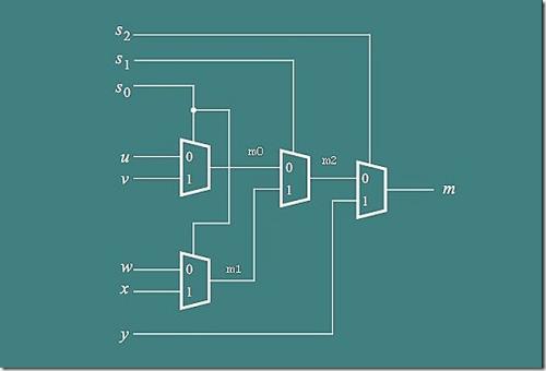
●multiplexer.v
This needs to take in all of the outputs from the cpu operation modules and the mode buttons, to output to the 7-segment display
This module should multiplex a single digit-to-7segment display.Digital Logic代写
Hint: These should be similar to a 4-1 multiplexer implementation, where each input of to the multiplexer is actually a full hex digit output from the different modules.
Start with designing a block diagram for the project before you go into coding. This is a requirement for the report. This should show how all your modules connect (a picture of what the Project1_top.v file is doing). You will need to assign a binary encoding for your module- operation combo, so I know how your button and switch input matches to your module- operation.
Deliverables Digital Logic代写
Below is a list of deliverables that need to be included in your project.
- Project Details: Title, partners, class, semester, software/hardwarerequirements
- Introduction: 1-paragraph introduction on what the project is including a block diagram of your design.
- Block Diagram. This should show all your modules connect (basically a picture ofwhat the Project1_top.v file is doing. Please submit this as a digital drawing (use draw.io or your favorite program to design this)
See https://www.smartdraw.com/block-diagram/#blockDiagramTypes
- A truth table showing your bitwise encoding mapping to the modes/operations of the project. Be sure to list how this maps to the
- Results: Explain how your design
- Pictures of each of the Modes/operations showing that the provided encoding matches the intended output for the given test outputs. Please use some digital editing to show how the switches match the(Powerpoint)
- Conclusion: 1-paragraph conclusive statement on the project. What was the most difficult part of this project? If something did not work, what is thereason and how would you correct it? What would you do different next time?
- Source Code: All Verilog files created for the
- (Extra Credit) A short demo to the instructor of the Knight Rider circuit in
Submitting your project:
Submit your project in a single .zip file containing the source code, technical report, and any other associated files. You do not need to send the Quartus project files.
Load your zip file to Canvas under the Project 1 assignment, as if it were homework.
Grading:
The project grade will be broken down as follows:
1. 10% Introduction and blockdiagram
2.60% Verilog modules (six modules x 10%each)
a. Coding correctness, following requirements, codereadability (comments where appropriate)
3.10% Description ofresults
4.10% Pictures of operational modes withdescriptions
5.10%Conclusion
6.+3 Extra credit – Knight Rider demo
更多其他:assignment代写 C++代写 CS代写 Data Analysis代写 essay代写 homework代写 java代写 java代码代写 java作业代写 os代写 project代写 python代写 report代写